Amplitude versus offset (AVO) analysis
| Development Geology Reference Manual | |

| |
| Series | Methods in Exploration |
|---|---|
| Part | Geophysical methods |
| Chapter | Amplitude versus offset (AVO) analysis |
| Author | Allan T. Long, R. C. Anderson |
| Link | Web page |
| Store | AAPG Store |
Components for AVO analysis
The amplitude versus offset (AVO) phenomena on seismic data can provide substantial exploration and development information. Under good conditions the information extracted can be as detailed as an elastic layered model of the earth in the vicinity of the exploration or development target. To accomplish this goal, a systems approach to the problem is used. Major components of such a system analysis procedure are as follows:
- AVO feasibility studies—Ascertain the general applicability of this technique to the problem at hand.
- Proper AVO data processing—Emphasize maintaining and enhancing the proper amplitude relationships.
- AVO scanning—Find anomalous regions of amplitude with offset on seismic data.
- Detailed AVO modeling supported by well log data—Provide base information upon which to judge and interpret the AVO study using well log data in the vicinity of an exploration target.
- Elastic model inversion at prospective locations—Identify potential reservoirs and describe them numerically prior to drilling.
Readers interested in additional information on AVO analysis should begin by consulting the work of Hilterman,[1] Neidell,[2] and Ostrander.[3]
AVO feasibility studies
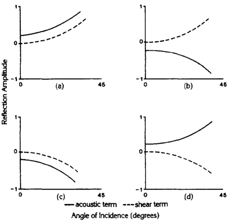
Figure 1 Possible combinations of the acoustic and shear terms.
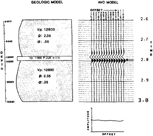
Figure 2 Brine sand model.
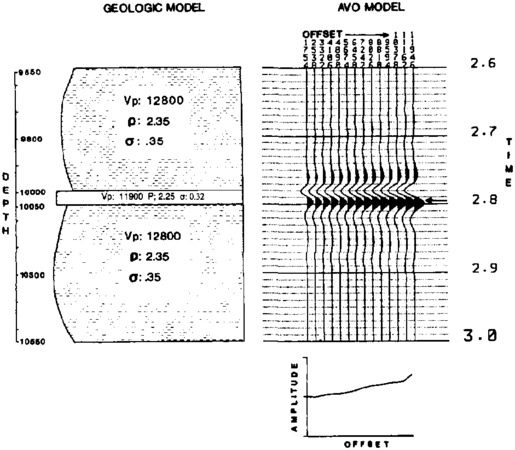
Figure 3 Gas sand model.


Whether or not there is an application for amplitude versus offset analysis in a given exploration setting is an often posed problem. The explorationist should ask several questions. Are the AVO phenomena that may be present large enough to overcome the various noises in the system? Are there sufficient differences between geological conditions and seismic expressions to distinguish between them?
A reflection coefficient (see seismic polarity) can be thought of as consisting of the sum of two components—an acoustic term and a shear term. The acoustic term depends only on the impedance of the two layers and the angle of incidence. The shear term depends on Poisson's ratio in the two layers and also on the angle of incidence.
An AVO response not only occurs from an interface characterized by a contrast in Poisson's ratio, but also from interfaces that are entirely acoustic—that is, the measured response is more than a simple contrast in Poisson's ratio.
Consequently, four response cases are possible, as shown in Figure 1. Two of these cases—(a) and (c)—represent constructive summation of the two terms, yielding a large AVO response. The other two cases—(b) and (d)—are destructive, and the total AVO response is small. A third case consisting of little shear response and strong acoustic response may produce high AVO and may not be associated with a Poisson's ratio contrast.
In addition to the acoustic and shear components of the AVO response, there are the effects of AVO tuning from thin beds. In contrast to normal incidence tuning, AVO tuning varies with offset and gives rise to amplitude and waveform changes concurrently.
Feasibility modeling requires the following: (1) a depth-velocity model, (2) density and velocity trend curves, (3) porosity ranges, (4) fluid content variation, (5) Poisson's ratio trend curves, and (6) a geological description of potential reservoir and encompassing environments. Figures 2 and 3 show model examples consisting of two fluid types. Figure 2 is a brine sand model, and Figure 3 is a gas sand model. The sensitivity of the seismic expression can now be studied by changing model parameters. If the model studies indicate measurable AVO responses, then AVO processing and interpretation techniques can be undertaken at an early stage in the exploration effort.
AVO data processing

Seismic data processing for AVO requires that certain steps be applied to common depth point (CDP) gathers (the individual traces prior to stacking). Areas of importance include (1) generalized amplitude corrections, (2) signal to noise ratio improvement, (3) robust deconvolution, and (4) prestack migration prior to AVO analysis in structurally complex areas.
Generalized amplitude corrections are probably the most important aspect in extracting and restoring proper amplitude relationships in the data. Amplitude corrections must compensate for (1) irregular source strength, (2) source array effects, (3) inelastic attenuation, (4) transmission loss effects, (5) spherical divergence, (6) receiver array effects, (7) receiver sensitivity, and (8) receiver vertical directivity.
Surface-consistent amplitude corrections are also necessary when amplitude variations in the data may relate to source and receiver environment and not to the geology. These corrections are distributed among the surface terms of source, receiver, and offset, plus a single subsurface (CDP or geological) term.
Normal moveout (NMO) and residual statics corrections must be performed as accurately as possible, for any AVO analysis is degraded by inappropriate corrections. The recent use of interactive processing workstations is providing explorationists with the necessary control over the selection of correct stacking velocities.
Signal to noise ratio improvements must occur on individual traces in the CDP gathers. Robust deconvolution is important to preserve stability of the wavelet across all offsets. In the land data case, a surface-consistent deconvolution method is usually desirable. To further stabilize the wavelet, deconvolve the data to a desired target waveform with frequency cutoffs predetermined by knowledge of the input data's usable frequency range. Trace-dependent deconvolution, such as a spiking operator, can sometimes produce severe distortions in reflector waveform when the signal to noise ratio is low on some of the individual traces.
Multiple interference can render amplitude with offset analysis of the CDP gathers meaningless. Generally, multiples are more dominant in data from the marine environment, but can also be strong in land data. Multiples are usually not visually evident in land data because of trace spacing and lower fold and will appear as strong random noise. But proper use of multiple removing programs, such as radon transform methods, can yield excellent results.
Figure 4 shows NMO-corrected CDP gathers that have been processed with the proper amplitude corrections and cascaded noise reduction methods. It is critical that noise be removed without smearing the signal or introducing artifacts, which often occurs with multichannel filtering techniques.
AVO scanning
The computer can efficiently measure the change in amplitude across the offsets of a CDP gather for each time sample and can produce a single number that is the best fit slope to that change in amplitude. This collection of numbers can be plotted like a seismic cross section to yield an amplitude versus offset gradient section. The gradient section can then be interpreted, and AVO anomalies can be correlated to the stack section, on which an interpreter has already identified key horizons and potential structural or stratigraphic trapping areas. The purpose of this step is to identify quickly regions of anomalous AVO behavior, which can then be studied further with detailed modeling and rock physics calibration.
AVO modeling
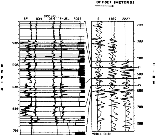
Figure 5 Gas well AVO model, involving blocked well logs and calibrated (wavelet-processed) seismic data.
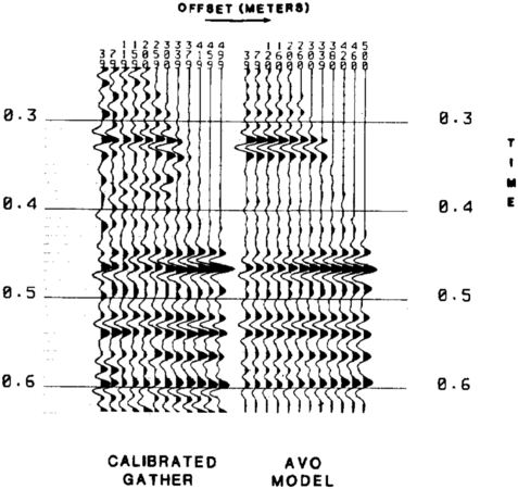
Figure 6 Comparison of calibrated seismic data and the gas well AVO model.


By using seismic data and available well logs, an understanding of the origin and nature of AVO phenomena can be realized by detailed modeling. A time match between seismic and well data can be found, along with the seismic wavelet for modeling. Then, using estimates of Poisson's ratio (empirically derived), elastic model inversions are performed to estimate a more precise Poisson's ratio.
The result of this approach applied to a gas sand problem is displayed in Figure 5. The AVO anomaly at 460 msec is the resultant response to this gas sand. An alternative display of calibrated CDP gathers and matched AVO model for the same gas sand problem is shown in the variable area plot in Figure 6.
AVO inversion
Amplitude versus offset anomalies at sites in the vicinity of previous detailed modeling can be inverted to obtain acoustic parameter information. Using the layered model from the previous step as the starting point for the inversion process, the final compressional velocity, density, and Poisson's ratio information can be found. This is then used to predict the probable geological circumstances at the inversion site.
A successful inversion of an AVO response provides the following:
- The origin of the anomaly, such as acoustic response, rigidity contrast, or AVO interference
- The thickness of the pay zone
- The value of Poisson's ratios near the anomaly
- The lithology, porosity, and fluid content of a given layer
See also
- Seismic data acquisition on land
- Seismic interpretation
- Cross-borehole tomography in development geology
- Synthetic seismograms
- Vertical and lateral seismic resolution and attenuation
- Forward modeling of seismic data
- Borehole gravity
- Displaying seismic data
- Three-dimensional seismic method
- Magnetics
- Full waveform acoustic logging
- Electrical methods
- Seismic migration
- Basic seismic processing
- Marine seismic data acquisition
- Introduction to geophysical methods
- Seismic data - mapping with two-dimensional data
- Seismic inversion
- Checkshots and vertical seismic profiles
- The gravity method
References
- ↑ Hilterman, F. J., 1990, Is AVO the seismic signature of lithology? A case history of Ship Shoal-South Addition: Geophysics—The Leading Edge, June, p. 15-22.
- ↑ Neidell, N. S., 1986, Amplitude variation with offset: Geophysics—The Leading Edge, March, p. 47–51.
- ↑ Ostrander, W. J., 1984, Plane-wave reflection coefficients for gas sands at nonnormal angles of incidence: Geophysics, v. 49, p. 1637–1648, 10, 1190/1, 1441571.
External links
| find literature about Amplitude versus offset (AVO) analysis |