Fluid flow fundamentals
| Development Geology Reference Manual | |

| |
| Series | Methods in Exploration |
|---|---|
| Part | Reservoir engineering methods |
| Chapter | Fundamentals of fluid flow |
| Author | Michael Golan |
| Link | Web page |
| Store | AAPG Store |
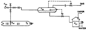
Well flow calculations focus essentially on two aspects of fluid flow: pressure profile along the flow path and the rate versus pressure relationship at key points of interest (nodes), as illustrated in Figure 1. The main parameters of interest (all in units of psia) are
- pR = reservoir pressure
- pwf = wellbore (bottomhole) flowing pressure
- pwh = wellhead pressure
- psp = separator pressure
- pST = stock tank pressure
The corresponding rates are
- qo = oil production rate (STB/day)
- qg = gas production rate (SCF/day)
The pressure difference (pR – pwf) is called the reservoir drawdown. It is the primary force driving reservoir fluids into the wellbore. Generally, production rates increase with increasing drawdown. How into the wellbore induced by drawdown is called inflow.
The relationship between the production flow rate measured at the stock tank, qo, and the bottomhole flowing pressure, pwf, is called the inflow performance relationship (1PR). The IPR of a well can be determined directly by production test data, or it can be predicted from reservoir data. Whether presented graphically or expressed by a formula, the IPR is a statement of the production capacity and is widely used to design and analyze the production performance of wells
Good general references on flow in reservoirs and wells include Golan and Whitson,[1] Bradley,[2] and Craft et al.[3]
Empirical IPR equations[edit]
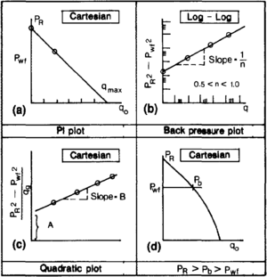
Several IPR formulas have been developed to represent the inflow behavior of various types of wells. Matching a formula to multi-rate production data (Figure 2) allows determination of the value of the characteristic constants in the equations, which in turn characterize the productivity of the well. The empirical formulas are the primary tools to quantify well productivity and to perform production calculations.
Productivity index equation for undersaturated oil[edit]
The production rate in undersaturated oil wells is linearly proportional to the drawdown, and the IPR is a straight line (Figure 2a). The equation is
The characteristic constant relating the oil rate to the drawdown is called the productivity index, f, and is defined as
with units of STB/day/psi. The productivity index states the numbers of STB/day produced for every psi of pressure drawdown and thus reflects the productivity or deliverability of the well.
When pwf equals atmospheric pressure, the rate is called absolute open flow (AOF) and is often designated as qmax. AOF is a useful indicator of well productivity.
Back pressure equations for saturated oil and gas wells[edit]
The equation for oil and gas wells is
It has two characteristic constants: the back pressure constant, c, and the back pressure exponent, n. The exponent n is a dimensionless number between 0.5 and 1.0. It approaches 1.0 for low rate wells and 0.5 for very high rate wells. Values of n and c can be determined graphically from a log-log plot of multiple rate test data in the form of (pR2 – pwf2) versus q (Figure 2b). The data point can be fitted to a straight line whose slope is 1/n.
Quadratic equation for saturated oil and gas wells[edit]
For saturated oil and gas wells, the equation is
The characteristic constants A and B are the corresponding slope and the intercept of the straight line obtained from a Cartesian plot of the multiple rate test data (Figure 2c) in the following form:
Extended range undersaturated oil IPR[edit]
For wells producing below bubblepoint pressure, pb while the reservoir pressure is above the bubblepoint (pwfbp
R), the IPR assumes the shape shown in Figure 2d. It can be represented by the following equations:
and
Extension of Darcy's law[edit]
Darcy's law, which was originally developed for water flow, has been extended to describe flow of hydrocarbon reservoir fluids (compressible and multiple phases).
For single-phase oil flow, the proportional constant that relates flow rates to pressure differences in the original Darcy's law is broken down into two independent factors: rock permeability, k, and fluid viscosity, μ For a linear flow system, this gives
The permeability is a property of the rock that reflects the “ease” with which the fluid flows through it. The viscosity is a property of the fluid and reflects the resistance of fluid to flow.
For multiple phase flow, the presence of a second phase in the porous media reduces the apparent permeability of the first phase (for example, the presence of gas reduces the apparent permeability of oil). The presence of each phase in the porous medium is quantified by the saturation, S, which is the ratio of fluid volume in a given porous rock to the pore volume of the rock:
where
- So = oil saturation (fraction)
- Sg = gas saturation (fraction)
- Vo = volume of oil in a given pore volume
- Vg = volume of gas in a given pore volume
- Vp = pore volume
The apparent or effective oil permeability, keo of one phase in the presence of a second phase can be arranged as the product of two terms: absolute permeability, ka, and relative oil permeability, kro:
The absolute permeability is a property of the rock and is essentially the permeability measured with single phase or at 100% single phase saturation. The relative permeability is a dimensionless quantity whose magnitude is between 1.0 and 0, depending on the saturation (Figure 3). Relative permeabilities are measured in core (petrophysical) laboratories, and the results are reported versus the saturation. Some laboratories normalize relative permeability values with values different than the single phase or 100% saturation value, so some caution needs to be taken in interpreting and using reported data.
Radial flow[edit]
Darcy's law can be applied to an ideal well model producing a constant steady-state production rate. The model assumes cylindrical flow in the reservoir where flow across the formation is horizontal and fluid moves radially toward the wellbore. It also assumes constant pay zone thickness, constant isotropic permeability, and an ideal liquid (homogeneous incompressible liquid in which viscosity is pressure independent).
For infinite size reservoirs, the result is
or in field units,
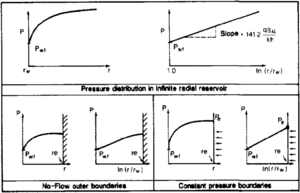
That is, for every radius r there is a corresponding pressure p that increases logarithmically with r (Figure 4).
Pressure distribution in radial bounded reservoirs is similar to the infinite case for the most of the drainage volume. It is different, however, near the boundaries, as shown in Figure 4.
Units of Darcy's law formulas[edit]
The practical field system is widely used for practical petroleum engineering calculations. It is a hybrid system that consists of various metric, English, and oil field units. It uses the millidarcy (md) for permeability. Other dimensions and units in this system are as follows:
- qo = stock tank oil rate (STB/day, or stock tank barrels per day)
- qg = gas flow rate (SCF/day, or standard cubic feet per day)
- μo = viscosity (cp, or centipoise)
- Bo = formation volume factor (RES bbl/STB, or reservoir barrels to stock tank barrels)
- pR = reservoir pressure (psia)
- pwf = bottomhole pressure (psia)
- k = permeability (md)
- h = pay zone thickness (ft)
- rw = wellbore radius (ft)
- re = radius of drainage (ft)
The formulas in the following section are in practical field units.
Restricted entry into the wellbore (Skin Effect)[edit]
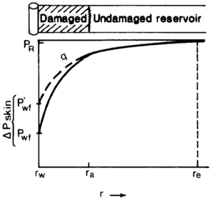
The actual pressure distribution differs in most cases from the ideal pressure distribution derived for the ideal model. The following additional pressure drop at the wellbore results from near wellbore phenomena (Figure 5):
The most important phenomena are usually flow convergence due to limited penetration of the pay zone (partial penetration), impaired permeability adjacent to the wellbore (formation damage), and flow restrictions in the perforations.
It is convenience to express Δpskin as a dimensionless quantity, s, called the skin factor, which is linearly proportional to Δpskin:
The skin factor can be determined from well test interpretation and can easily be converted to actual Δpskin or Pwf(actual)*
Theoretical pressure-rate relationship (IPR)[edit]
Darcy's law applied to the ideal well model gives an IPR equation expressed in terms of reservoir parameters. For undersaturated oil (a single-phase homogeneous liquid) in radial reservoir with no-flow outer boundaries, the following equation applies:
This equation is in harmony with the empirical IPR equation for single-phase oil, where
Radius of drainage[edit]
The radius of drainage to be used in the radial flow equation and the productivity index expression is
where A is the well's drainage area in square feet and the radius is in feet. If the drainage area is given in acres, it has to be converted to square feet using the relationship 1 acre = 43,560 ft2.
Expansion of the ideal well model[edit]
The theoretically derived IPR equations can be expanded to include the production of gas and saturated oil. For low pressure gas reservoirs (below 2000 psia), the following equation is used:
where
- qg = gas flow rate (SCF/day)
- T = temperature(R° = F° + 460)
- Z = gas compressibility factor
- μg = gas viscosity (cp)
All the other parameters have the same units as the oil flow equations. There are rigorous methods used to express IPR of gas wells at reservoir pressures higher than 2000 psia. However, the low pressure equation is good for most well productivity calculations.
For saturated oil (simultaneous oil and gas flow), the equation used is
where the term kro/μoBo is evaluated at average reservoir pressure, pR, and saturation conditions.
There are two practical considerations to keep in mind when using these equations. First, depending on well spacing, the value of ln (re/rw) is in the range of 6.5 to 8. A value of 7 is a good approximation in most productivity calculations. Second, the skin factor, s, is positive when the entry to the wellbore is restricted by the skin effect. It is negative if the productivity is better than predicted by the ideal radial model (for example, in stimulated or fractured wells).
IPR derived from reservoir simulation[edit]
For the particular case of a solution gas drive reservoir, there is an IPR formula derived by fitting an equation to the results from computer simulations performed for a wide variety of wells with a wide range of reservoir parameters. The formula given in normalized form is
This formula is useful for low rate oil wells. It overestimates the productivity of high rate wells (those producing more than 2000 STB/day).
Example:
A well in a solution gas drive reservoir has a reservoir pressure of 4000 psia. A single test point is qo = 200 STB/day with pwf = 3220 psia. Substituting the data in the IPR equation and solving for qmax gives
Substituting the calculated qmax and the given pR in the equation calculates points on the IPR, as follows:
| pwf (psia) | qo (STB/day) |
|---|---|
| 4000 | 0 |
| 3000 | 250 |
| 2000 | 437 |
| 1500 | 508 |
| 1000 | 562 |
Effect of depletion on IPR formulas[edit]
Depletion usually results in deterioration of the IPR (Figure 6). These changes can be predicted quantitatively by calculating the changes of the characteristic constants: j, c, qax A, and B. The exponent n does not change with depletion. If subscript p denotes the present depletion state and subscript f a future state, the present and future characteristic factors are related as follows:
For undersaturated oil reservoirs:
Low pressure gas reservoirs:
Saturated oil reservoirs:
or
where nf = np, = n.
Example:
The present state IPR of an oil well in a solution gas drive reservoir is
where
Additional reservoir data are as follows:
| pR (psia) | kro/μoBo (cp-l) |
|---|---|
| 4000 | 0.223 |
| 3520 | 0.147 |
At a future stage where pR = 3520 psia, the maximum rate will be
Assuming that n does not change with depletion, the new IPR equation at pR = 3520 psia is
Effect of stimulation and damage on IPR equations[edit]
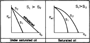
Stimulating a well and reducing its skin factor improve the IPR of a well (Figure 7). Using the subscript 1 to denote a prestimulation or preservice state and the subscript 2 to denote a new post-treatment state, we see the characteristic parameters in IPR equation change with changing skin factor as follows:
Undersaturated oil reservoirs:
Saturated oil and gas reservoirs:
or
where n1 = n2 = n.
See also[edit]
- Enhanced oil recovery
- Drive mechanisms and recovery
- Reservoir modeling for simulation purposes
- Reserves estimation
- Waterflooding
- Conducting a reservoir simulation study: an overview
- Introduction to reservoir engineering methods
- Petroleum reservoir fluid properties
References[edit]
- ↑ Golan, M., and G. H. Whitson, 1991, Well Performance, 2nd. ed.: Englewood Cliffs, NJ, Prentice Hall.
- ↑ Bradley, H. B., ed., 1987, Petroleum Engineering Handbook: Richardson, TX, Society of Petroleum Engineers.
- ↑ Craft, B. C., M. Hawkins, and R. E. Terry, 1991, Applied Petroleum Reservoir Engineering, 2nd. ed.: Englewood Cliffs, NJ, Prentice Hall, p. 210–263.






![{\displaystyle q_{\rm {o}}={\frac {kh(p_{\rm {R}}-P_{\rm {wf}})}{141.2\mu _{\rm {o}}B_{\rm {o}}[\ln(r_{\rm {e}}/r_{\rm {w}})-0.75+s]}}}](https://wikimedia.org/api/rest_v1/media/math/render/svg/bdf55ee73d92e67be64a7be7a6a88e94587874ab)
![{\displaystyle J={\frac {q_{\rm {o}}}{p_{R}-p_{wf}}}={\frac {kh}{141.2\mu _{\rm {o}}B_{\rm {o}}[\ln(r_{\rm {e}}/r_{\rm {w}})-0.75+s]}}}](https://wikimedia.org/api/rest_v1/media/math/render/svg/895652cd7871cbd8dff9f5aa5bc88eec03e72677)

![{\displaystyle q_{\rm {g}}={\frac {0.703kh(p_{\rm {R}}^{2}-p_{\rm {wf}}^{2})}{T\mu _{\rm {g}}Z[\ln(r_{\rm {e}}/r_{\rm {w}})-0.75+s]}}}](https://wikimedia.org/api/rest_v1/media/math/render/svg/963eb6d1723a427378037c91f1b4690fb9c55f72)
![{\displaystyle q_{\rm {o}}={\frac {kh}{141.2[\ln(r_{\rm {e}}/r_{\rm {w}})-0.75+s]}}{\frac {k_{\rm {ro}}/\mu _{\rm {o}}B_{\rm {o}}}{2p_{\rm {R}}}}(p_{\rm {R}}^{2}-p_{\rm {wf}}^{2})}](https://wikimedia.org/api/rest_v1/media/math/render/svg/f7ea0e304e545b25fe47a61f05ef1268240fa0cd)


![{\displaystyle {\frac {c_{f}}{c_{p}}}=\left[{\frac {(k_{\rm {ro}}/\mu _{\rm {o}}B_{\rm {o}})_{\rm {f}}}{(k_{\rm {ro}}/\mu _{\rm {o}}B_{\rm {o}})_{\rm {p}}}}{\frac {(p_{\rm {R}})_{\rm {f}}}{(p_{\rm {R}})_{\rm {p}}}}\right]^{n}}](https://wikimedia.org/api/rest_v1/media/math/render/svg/b2b7b825d22d3f82a048c54b5918769ed6327a32)
![{\displaystyle {\frac {(q_{\rm {o\ max}})_{\rm {f}}}{(q_{\rm {o\ max}})_{\rm {p}}}}=\left[{\frac {(k_{\rm {ro}}/\mu _{\rm {o}}B_{\rm {o}})_{\rm {f}}}{(k_{\rm {ro}}/\mu _{\rm {o}}B_{\rm {o}})_{\rm {p}}}}{\frac {(p_{\rm {R}})_{\rm {f}}}{(p_{\rm {R}})_{\rm {p}}}}\right]^{n}}](https://wikimedia.org/api/rest_v1/media/math/render/svg/39f6a68cc2a0cc11010112f3dd84b05a71703c51)
![{\displaystyle q_{\rm {o}}/q_{\rm {o\ max}}=[1-(p_{\rm {wf}}/p_{\rm {R}})^{2}]^{n}}](https://wikimedia.org/api/rest_v1/media/math/render/svg/884074689e51c82408331d6fe67a5cb0b6907f5e)


![{\displaystyle q_{\rm {max}}=\left[{\frac {(0.147)(3520)}{(0.223)(4000)}}\right]^{0.8}=310{\mbox{ STB/day}}}](https://wikimedia.org/api/rest_v1/media/math/render/svg/cd25178da7096c486cfe19b79bf34dd6ba4d74b9)
![{\displaystyle q_{\rm {o}}=310[1-(p_{\rm {wf}}/3620)^{2}]^{0.8}}](https://wikimedia.org/api/rest_v1/media/math/render/svg/c6acbc41ad400543cc33bc2085abfa1d353e84cb)
![{\displaystyle {\frac {J_{2}}{J_{1}}}={\frac {[\ln(r_{\rm {e}}/r_{\rm {w}})-0.5+s]_{1}}{[\ln(r_{\rm {e}}/r_{\rm {w}})-0.5+s]_{2}}}}](https://wikimedia.org/api/rest_v1/media/math/render/svg/bc66228e23f6ebb8d07d65abe1aa2896c7c77df6)
![{\displaystyle {\frac {c_{2}}{c_{1}}}=\left\{{\frac {[\ln(r_{\rm {e}}/r_{\rm {w}})-0.5+s]_{1}}{[\ln(r_{\rm {e}}/r_{\rm {w}})-0.5+s]_{2}}}\right\}^{2n-1}}](https://wikimedia.org/api/rest_v1/media/math/render/svg/409d9736b355f62504364348a02b288c89fc9039)
![{\displaystyle {\frac {(q_{\rm {o\ max}})_{2}}{(q_{\rm {o\ max}})_{1}}}=\left\{{\frac {[\ln(r_{\rm {e}}/r_{\rm {w}})-0.5+s]_{1}}{[\ln(r_{\rm {e}}/r_{\rm {w}})-0.5+s]_{2}}}\right\}^{2n-1}}](https://wikimedia.org/api/rest_v1/media/math/render/svg/e9217357afb05842ced79fc30b96a5aa4704af23)