Stimulation
| It has been suggested that some portions of this article be split into multiple articles. |
| Development Geology Reference Manual | |

| |
| Series | Methods in Exploration |
|---|---|
| Part | Production engineering methods |
| Chapter | Stimulation |
| Author | John L. Gidley |
| Link | Web page |
| Store | AAPG Store |

The need for well stimulation arises from either one of the following conditions:
- Formation permeability is inadequate to allow the well to produce at rates high enough for the timely recovery of investment in drilling and completing the well.
- The well has been completed in a formation having adequate permeability, but the formation near the wellbore has been damaged by the drilling or completion process.
The first case, low formation permeability, requires a reservoir stimulation technique, which can be either hydraulic fracturing or acid fracturing. The second case, formation damage, requires a damage removal technique, which is usually matrix acidizing but may occasionally involve hydraulic fracturing. Solvent or surfactant treatments are sometimes used for damage removal.
Figure 1 illustrates the division of well stimulation problems on the basis of formation permeability. Formations having an average effective permeability of 1 mD (millidarcy) or less generally require reservoir stimulation methods, while those having effective permeabilities of 10 md or greater generally require damage removal methods. Those formations in between these two permeabilities may require either type of treatment.
A few examples may serve to illustrate this method of classifying well stimulation problems. The “tight gas sands” of the Rocky Mountain area have effective permeabilities often in the microdarcy range (1 μD, or microdarcy, = 0.001 mD). If economic completions are to be developed from such formations, hydraulic fracturing (a reservoir stimulation method) must be used to stimulate reservoir performance (see Evaluating tight gas reservoirs).
In contrast, the younger permeable formations along the Gulf Coast, such as those of Miocene age, often have very high permeabilities—commonly, several hundred millidarcies. When such formations are unproductive upon initial completion, it often indicates severe formation damage. Although hydraulic fracturing methods have occasionally been employed to stimulate such wells, sandstone acidizing techniques, which are capable of removing near-wellbore damage, are normally the preferred stimulation method.
Hydraulic fracturing
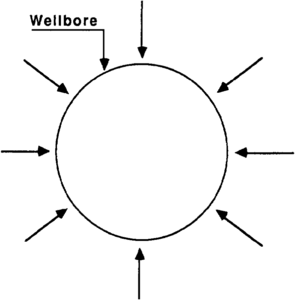
Figure 2 Flow to unfractured well converges at wellbore.
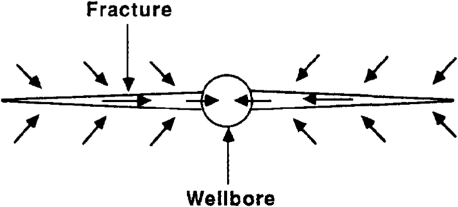
Figure 3 Flow to fractured well is linear to fracture, followed by flow that is down fracture to the well bore.


The purpose of hydraulic fracturing is to change the flow pattern in the reservoir from one that converges radially on the well bore (Figure 2) with flow resistance concentrated near the wellbore, to one where flow in the reservoir is linear to a highly conductive fracture that conducts fluid to the wellbore with minimal flow resistance (Figure 3). The success of this operation depends upon the conductivity of the hydraulic fracture and how successfully this conductivity can be retained following the treatment. These, in turn, depend largely upon the design and execution of the fracturing treatment.
Fracturing treatment

A hydraulic fracture is created in a subsurface formation when a fluid is pumped into that formation at a rate faster than the formation can accept the fluid through its matrix permeability. For example, Figure 4 illustrates the pressure versus time behavior at the surface of a well that is being fractured. As fluid is pumped into the target formation at a rate sufficient to fracture the well, the pressure at the formation face builds up rapidly to the point that the formation fails and a fracture is developed.
Continued injection at high rate causes the fracture to extend from the wellbore, and this growth in fracture length is accompanied by an increase in fracture width at the wellbore and proportionately throughout the fracture. The fluid being pumped in the fracture at this time contains no proppant and is often referred to as the “pad.” Its success in extending the fracture depends upon how much of the fluid injected can be retained within the fracture. Leak-off through the face of the fracture reduces the amount of fluid retained in the fracture. Only that fluid retained within the fracture is effective in extending the fracture. To reduce fluid leak-off, certain materials are added to the fracturing fluid to form a filter cake on the face of the fracture and to plug the porosity and permeability of the face of the fracture.

As fracture width grows, a point is soon reached where the fracture can accept a propping agent, and the proppant is added to the fracturing fluid (Figure 5). Typically, proppant is added initially at a low concentration (about weight::1 lb of proppant per gallon of fracturing fluid), then the concentration is subsequently increased as it becomes apparent that the lower concentrations of proppant are being accepted by the fracture. The purpose of the proppant is to hold the fracture open. Common proppant materials include sand, resin-coated sand, and ceramic beads.
When the desired amount of proppant has been pumped into the fracture, pumping is ceased. The fracture begins to close while the system remains shut in, as shown in Figure 6. After a few minutes or hours, depending on the conditions, the surface valves are opened and fluid is produced at the surface from the fracture. This cleanup period is designed to remove the fracturing fluid from the formation and to initiate the production of reservoir fluids. Reservoir “cleanup” occurs over a period of several days for relatively permeable wells to a period of weeks or months for low permeability wells. Typically, during the cleanup period, only 30–70% of the fracturing fluid used in the operation is recovered. However, the success or failure of the fracture treatment does not usually correlate with the percentage of fluid recovery during the cleanup period.
Rather, the success or failure of the fracturing treatment depends more upon how successfully the proppant was placed in the fracture, the conductivity of the proppant within the fracture after the treatment, and the potential of the well as an appropriate stimulation candidate, in other words, its remaining reservoir pressure, reserves, and other considerations. In some formations, where the hydrocarbon is located predominantly in natural fractures, the success of the treatment depends upon the orientation of the hydraulic fracture relative to the preferred direction of the natural fractures.
Fracture orientation
A hydraulic fracture will propagate in a plane perpendicular to the least principal earth stress. For example, consider a well at depth::1000 ft in a tectonically relaxed area with a terrastatic gradient of 1.0 psi/ft of depth. In such a shallow well, the overburden stress can be overcome more easily than either of the two principal horizontal stresses. If an attempt is made to fracture such a well by pumping into it at high injection rates, the pressure adjacent to the exposed formation will increase rapidly. When that pressure becomes 1000 psi or slightly greater, there is sufficient pressure to lift the overburden. At this point, a horizontal fracture occurs (that is, a fracture perpendicular to the vertical wellbore or parallel to the surface of the earth).
Alternatively, consider a well that is depth::5000 ft deep in a formation having an average terrastatic gradient of 1.0 psi/ft and is also in a tectonically relaxed area. When an attempt is made to fracture this well hydraulically, it is found that a fracture can be propagated with a bottomhole pressure of 3500 psi. Since this pressure is inadequate to lift the overburden weight of the earth, it is inferred that the fracture is not horizontal but rather vertical (that is, in the plane of the vertical axis of the wellbore). Consequently, a good rule of thumb is that in wells deeper than about depth::2000 ft, in tectonically relaxed areas, most hydraulic fractures will be vertical.
The azimuth direction of the hydraulic fracture depends upon the relative magnitude of the two principal horizontal stresses. Contrary to certain folk lore, there is no effective method for redirecting the direction of a vertical fracture in a deep well (2000 ft or deeper). It depends entirely upon the relative magnitude of the two principal horizontal stresses in the neighborhood of the wellbore. The hydraulic fracture will propagate perpendicular to the least principal stress. Fracture orientations tend to remain roughly the same over large geographical areas. East of the Rocky Mountain area, vertical fractures tend toward a northeasterly direction. This orientation is altered somewhat in the Gulf Coast area where fractures seem to parallel the coast line. In the Rocky Mountain area, fractures occur in unpredictable directions that are highly dependent upon the direction of local tectonic forces.
Fracturing fluids and proppant placement
The effectiveness of a fracturing treatment is largely dependent upon how successfully the proppant has been placed within the productive zone and how much conductivity the propped fracture has relative to that of the formation being stimulated.
Placement of the proppant within the fracture is governed by the properties of the fracturing fluid. Certain fluids totally suspend the proppant during its transit down the wellbore and into the fracture. Other fluids allow the proppant to drop through the fluid after the fluid and proppant enter the fracture. The first category of fluids is often referred to as perfect support fluids, whereas the second is described as equilibrium bank fluids.
Perfect support fluids are created by adding to the fracturing fluids materials that are chemically reactive and capable of developing structure within the fluid. Guar gum, a natural product from the guar bean, builds viscosity in water. In addition, certain materials, typically organometallic compounds, react with solutions of guar gum and build structure by “cross-linking” the guar polymers. These fluids, when properly designed and formulated, permit the suspension of the proppant within the fracture throughout the fracture closure period. By this means, proppant distribution throughout the fracture can be made to conform to that designed in the treatment.
In very hot wells, especially those treated at high pumping rates, cross-linked fluids will lose most of their viscosity by shear degradation during the pumping process and through exposure to high temperatures. If these fluids lose viscosity, they also lose their ability to suspend the proppant. This problem has been corrected with the development of delayed, cross-linked gelled fracturing fluids. Such fluids first became available during the early 1980s. They are capable of retaining their viscosity within the fracture even under the severe conditions described.
The second type of fracturing fluid, equilibrium bank fluids, allow the proppant to fall through the fracturing fluid and settle in an equilibrium bank that builds away from the wellbore. Such fluids may provide a fracture completely filled with proppant near the wellbore, but the height of the proppant bank decreases rapidly with distance away from the wellbore. These fluids have application in damage removal treatments where short, highly conductive fractures are required, but they have limited utility in creating long fractures with high conductivity.
Fracture conductivity

An important factor affecting the success or failure of a hydraulic fracture treatment is the conductivity (in situ) of the fracture developed. The role of this variable can be illustrated by a graph (Figure 7), first presented by McGuire and Sikora in 1960. This graph shows how the productivity index ratio (J/Jo shown on the vertical axis) developed by the treatment relates to the fracture length and the permeability contrast between the propped fracture and the permeability of the formation.
Suppose a well that is depth::6000 ft deep is fractured and the confining stress on the proppant under the most severe producing condition will be 4000 psi. If a 20/40 mesh Ottawa sand is used during the treatment, the permeability of this sand will be about 100 D (darcys). Suppose that the width of the propped fracture created is only length::0.1 in. after fracture closure and that a 0.1-mD formation is being stimulated. Assume that the well is on 40-acre spacing; therefore, the scale factors in Figure 7 are 1.0 for both the vertical and horizontal axes. Also assume that a propped fracture length of length::660 ft has been created. This means the fracture extends to the radius of drainage for this well.
The McGuire-Sikora graph indicates that this treatment will result in a relative conductivity of 105, L/re = 1.0 (where L is the length of the fracture and re the drainage radius), and a stimulation ratio of about 11.5. That is, the well after fracturing should have a stabilized production rate of about 11.5 times the production rate prior to stimulation. This prediction assumes that the value of skin prior to the fracture treatment was zero (that is, no stimulation and no damage).
If this same treatment had been applied to a reservoir with permeability of 10 mD instead of 0.1 mD, the relative conductivity would have been reduced by a factor of 100 (that is, to 103). For this case, the stimulation ratio would have been slightly greater than 2 as compared to 11.5 for the 0.1-mD reservoir. To improve stimulation in the high permeability reservoir, a proppant having a permeability substantially greater than that of the Ottawa sand in the previous example would need to be used. However, even the best available 20/40 mesh proppants have a permeability only about four times greater than sand at these low confining stresses. Thus, the ability to improve the response is limited to the permeability of the propping agent that can be afforded for each treatment. The other choice is to increase the packed fracture width. Fractures four or five times wider are possible, but are often difficult to create. Hence, highly permeable formations are difficult to stimulate with the existing materials and techniques now available by hydraulic fracturing, unless the formation has been damaged during the drilling or completion operations.
Geological considerations important in fracturing
All types of productive formations can be stimulated by hydraulic (proppant) fracturing, including sandstones, carbonates, cherts, and shales. The main requirements for success in fracturing a well are that the formation contain hydrocarbons and have some natural permeability (whether through natural fractures or within the matrix) to allow oil and gas to reach the hydraulic fracture. However, perhaps the single most important parameter that should be known prior to considering a well as a candidate for fracturing is the formation permeability. High permeability makes a well difficult to stimulate by fracturing, while low permeability formations can easily be stimulated by hydraulic fracturing.
The location of confining shales is also important in fracturing. If the productive formation is effectively isolated between two massive shales that may serve as barriers to the vertical extension of the fracture, then the hydraulic fracture will be confined, the fracturing fluid and materials can be concentrated upon the productive formation, and the treatment will normally be successful. Thus, certain lithological sequences are more conducive to effective stimulation by fracturing than others.
Acidizing
Acidizing can be divided into three types of operations:
- Acid fracturing, which involves injecting acid at rates above those that will be accepted by the matrix, fracturing the formation, and etching the face of the fracture to develop a permeable flow path
- Matrix acidizing, which involves injecting acid at low rates to permit the uniform penetration of the formation without fracturing it
- Acid washing, which involves using acid to dissolve scales and precipitates within the wellbore by moving acid across the encrusted surfaces. The acid used in acid washing seldom enters the formation and for that reason is not discussed further.
Acid fracturing
Acid fracturing is accomplished in a manner very similar to that described for hydraulic fracturing. The only significant difference is that it involves formations that have significant solubility to acid and no proppant is used during the treatment. Instead, as the fracture is created, acid etches the face of the fracture. The regions that are etched most deeply supply the fracture porosity and conductivity needed to improve flow to the wellbore.
The acid used in acid fracturing is normally hydrochloric acid (HCl). Occasionally, organic acids such as formic or acetic acid may be used, either alone or in mixtures with hydrochloric acid. Organic acids are used principally in hot wells (>temperature::250°F) to reduce the corrosiveness of the acid mixture.
Hydrochloric acid is commonly used in acid fracturing because of its low cost per unit of dissolving power (hydrogen ion concentration) and because it develops soluble salts (principally the chlorides of calcium and magnesium) when reacted with limestone or dolomite.
Typically, 15% (by weight) HCl is used, and this is often referred to as “regular” acid. Half strength acid (7.5% HCl) is used in some applications in which dissolving power is not the main consideration. Double strength acid (28% HCl) has found application in certain areas, but the higher strength is more corrosive and requires more effective inhibitors than 15% HCl.
Acid fracturing is confined to the stimulation of carbonates. Acid fracturing is not useful for stimulating sandstone formations because the acids reactive with sandstones, such as hydrofluoric-hydrochloric acid (HF/HCl) do not provide the differential etching on sandstones in the manner that hydrochloric acid does on limestones or dolomites.
Acid fracturing has both advantages and disadvantages relative to proppant fracturing (which may also be used on carbonates). Among the advantages of acid fracturing are that the operation can be carried out in the field with little risk of mechanical failure. Fracture treatments carrying propping agents will sometimes screen out; such failures do not occur with acid fracturing. In addition, acid fracturing can often be carried out for less expense than proppant fracturing because of the use of less equipment (for example, no proppant handling equipment or blender is required with acid fracturing). Finally, acid fracturing can be designed with somewhat less sophisticated tools than proppant fracturing and thus can often be accomplished with greater certainty.
The disadvantage of acid fracturing is that fluid loss during the fracturing operation cannot be controlled as effectively in as in proppant fracturing since the acid reacts with the formation and often bypasses the material being used to reduce fluid loss. Normally, fracture half-lengths of only 50–200 ft can be achieved with acid. The net effect is that acid fracturing cannot be used to create long fractures, especially in reservoirs with temperatures above temperature::200°F. To create long fractures in low permeability carbonates, hydraulic fracture treatments carrying a propping agent should be used. In many cases, the choice between proppant fracturing and acid fracturing can be made only after a thorough evaluation of the potential and limitations of each treatment for the specific job intended.
Matrix acidizing
Matrix acidizing is used to enlarge the pore spaces for fluid flow by dissolving the pore lining materials. Matrix acidizing of limestone formations involves simply enlarging the pores by dissolving part of the matrix. Matrix acidizing of sandstone formations is almost always directed at dissolving pore lining materials such as clays that may adversely affect the permeability of the system when exposed to fluids from the drilling or completion operation. (For more on fluid-rock interactions, see the chapter on “Rock-Water Interactions: Formation Damage” in Part 5.)
Matrix acidizing is simply a damage removal operation. Even in limestones, the amount of acid required to provide reservoir stimulation by dissolving formation and enlarging the wellbore can readily be shown to be exorbitant. Thus, in limestones this technique is often used to overcome near-wellbore damage, such as that caused in the perforating process, or to bypass plugged porosity caused by drilling or completion operations. True matrix acidizing is used very little in carbonates since these materials are not as susceptible to formation damage as are sandstones.
Matrix acidizing is mainly used in sandstone formations. Both hydrochloric acid and mixtures of HF/HCl acid are used in matrix acidizing. Hydrochloric acid is often an effective stimulant in formations that contain some soluble carbonate. In this case, dissolving the carbonate develops an alternate path for fluid flow and provides a measure of stimulation.
More frequently, mixtures of HF/HCl acid are required to stimulate formations where the damage resides in the clay fraction. The corrective action is to dissolve the clays near the wellbore and remove them completely. By this means, the zone most susceptible to damage during drilling or completion operations is cleaned of the material.
The acid formulation usually employed contains 3% HF (hydrofluoric acid) and 12% HCl. At higher temperatures, mixtures of 1.5% HF and 6% HCl appear to be more effective than the 3% HF formulation.
Mixtures of HF/HCl acid require greater care in their application than does HCl alone. For example, HF reacts with the sodium in formation waters to produce insoluble fluorosilicates or with calcium to form CaF2, an insoluble precipitate. For this reason, a spacer fluid must be used ahead of an HF/HCl treatment to displace the connate water. HF/HCl treatments, especially on oil-bearing formations, require an afterflush containing additives and solvents to clean up the products of reaction and avoid emulsification of the crude with acid byproducts. Certain mutual solvents are useful as additives in the afterflush to effect cleanup.
See also
- Introduction to production engineering methods
- Artificial lift
- Well completions
- Production problems
- Workovers
External links
| find literature about Stimulation |