Difference between revisions of "Seismic survey components"
Cwhitehurst (talk | contribs) |
Cwhitehurst (talk | contribs) m (added Category:Treatise Handbook 3 using HotCat) |
||
| (11 intermediate revisions by 3 users not shown) | |||
| Line 6: | Line 6: | ||
| part = Predicting the occurrence of oil and gas traps | | part = Predicting the occurrence of oil and gas traps | ||
| chapter = Interpreting seismic data | | chapter = Interpreting seismic data | ||
| − | | frompg = 12- | + | | frompg = 12-10 |
| − | | topg = 12- | + | | topg = 12-10 |
| author = Christopher L. Liner | | author = Christopher L. Liner | ||
| link = http://archives.datapages.com/data/specpubs/beaumont/ch12/ch12.htm | | link = http://archives.datapages.com/data/specpubs/beaumont/ch12/ch12.htm | ||
| Line 16: | Line 16: | ||
==Midpoints== | ==Midpoints== | ||
| − | To transmit energy into the subsurface, a shot is fired on the earth's surface. Many seismic receivers record the resulting echoes from underlying strata. Each receiver records the echoes in a trace called a '''prestack trace'''. Each prestack trace has a source and receiver coordinate, but the trace is plotted at the point halfway between the source and receiver pair, called the midpoint. The seismic method is designed so several prestack traces have the same midpoint. | + | To transmit energy into the subsurface, a shot is fired on the earth's surface. Many seismic receivers record the resulting echoes from underlying strata. Each receiver records the echoes in a [[trace]] called a '''[[prestack trace]]'''. Each prestack trace has a source and receiver coordinate, but the trace is plotted at the point halfway between the source and receiver pair, called the midpoint. The seismic method is designed so several prestack traces have the same midpoint. (For more information about acquisition, please see [[Seismic data acquisition on land]] and [[Marine seismic data acquisition]].) |
==Bins== | ==Bins== | ||
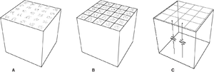
| − | [[file:interpreting-seismic-data_fig12-4.png|thumb|{{figure number|1}}Illustration of the bin concept. Copyright: Liner,<ref name=Liner>Liner, C., 1999, Elements of 3-D Seimology: Tulsa, PennWell</ref> courtesy PennWell.]] | + | [[file:interpreting-seismic-data_fig12-4.png|300px|thumb|{{figure number|1}}Illustration of the bin concept. Copyright: Liner,<ref name=Liner>Liner, C., 1999, Elements of 3-D Seimology: Tulsa, PennWell</ref> courtesy PennWell.]] |
| − | For 2-D seismic, the prestack | + | For 2-D [[seismic data]], the [[prestack trace]]s are sorted into groups associated with one midpoint on the earth's surface. The 3-D seismic data are sorted into discrete areas called bins. All actual midpoints that fall into the bin area belong to that bin. In effect, a grid is laid over the actual midpoints. Each bin has an in-line and cross-line dimension. The [[fold]] of each bin is the number of traces captured by that bin. Through the [[Basic seismic processing#Common midpoint (CMP) stack|stacking]] process, all traces within a bin are summed to create a single stack trace, greatly improving signal quality. |
| − | [[:file:interpreting-seismic-data_fig12-4.png|Figure 1]] illustrates the bin concept. The actual midpoints for a well-designed and executed survey will show natural clustering (A). On this cloud of midpoints we impose a grid of bins, each bin capturing all traces whose midpoints lie in it (B). After processing (stacking, migration, etc.), there is one trace at the center of each bin (C). These are the poststack data traces we interpret. | + | [[:file:interpreting-seismic-data_fig12-4.png|Figure 1]] illustrates the bin concept. The actual midpoints for a well-designed and executed survey will show natural clustering (A). On this cloud of midpoints we impose a grid of bins, each bin capturing all traces whose midpoints lie in it (B). After processing (stacking, [[Seismic migration|migration]], etc.), there is one trace at the center of each bin (C). These are the [[poststack trace|poststack]] data traces we interpret. |
==See also== | ==See also== | ||
| Line 40: | Line 40: | ||
* [http://store.aapg.org/detail.aspx?id=545 Find the book in the AAPG Store] | * [http://store.aapg.org/detail.aspx?id=545 Find the book in the AAPG Store] | ||
| − | |||
[[Category:Interpreting seismic data]] | [[Category:Interpreting seismic data]] | ||
| + | [[Category:Treatise Handbook 3]] | ||
Latest revision as of 19:05, 27 January 2022
| Exploring for Oil and Gas Traps | |

| |
| Series | Treatise in Petroleum Geology |
|---|---|
| Part | Predicting the occurrence of oil and gas traps |
| Chapter | Interpreting seismic data |
| Author | Christopher L. Liner |
| Link | Web page |
| Store | AAPG Store |
Midpoints
To transmit energy into the subsurface, a shot is fired on the earth's surface. Many seismic receivers record the resulting echoes from underlying strata. Each receiver records the echoes in a trace called a prestack trace. Each prestack trace has a source and receiver coordinate, but the trace is plotted at the point halfway between the source and receiver pair, called the midpoint. The seismic method is designed so several prestack traces have the same midpoint. (For more information about acquisition, please see Seismic data acquisition on land and Marine seismic data acquisition.)
Bins

For 2-D seismic data, the prestack traces are sorted into groups associated with one midpoint on the earth's surface. The 3-D seismic data are sorted into discrete areas called bins. All actual midpoints that fall into the bin area belong to that bin. In effect, a grid is laid over the actual midpoints. Each bin has an in-line and cross-line dimension. The fold of each bin is the number of traces captured by that bin. Through the stacking process, all traces within a bin are summed to create a single stack trace, greatly improving signal quality.
Figure 1 illustrates the bin concept. The actual midpoints for a well-designed and executed survey will show natural clustering (A). On this cloud of midpoints we impose a grid of bins, each bin capturing all traces whose midpoints lie in it (B). After processing (stacking, migration, etc.), there is one trace at the center of each bin (C). These are the poststack data traces we interpret.
See also
References
- ↑ Liner, C., 1999, Elements of 3-D Seimology: Tulsa, PennWell