Land rigs
| Development Geology Reference Manual | |

| |
| Series | Methods in Exploration |
|---|---|
| Part | Wellsite methods |
| Chapter | Land rigs |
| Author | Byram Reed |
| Link | Web page |
| Store | AAPG Store |
Parts of a rig[edit]
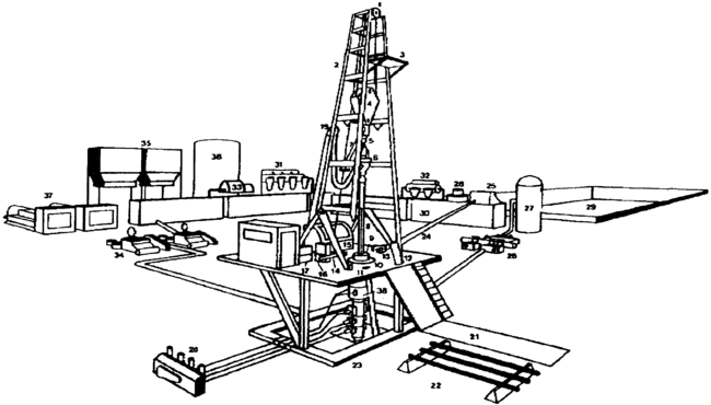
The parts of the rig can be grouped into five systems (Figure 1):
- Power
- Rotating
- Hoisting
- Circulating
- Control and measurement
Power system[edit]
Power is provided to the rig by diesel engines, diesel-electric engines, or in some cases, butane engines. Power is transferred from the engines to the different rig systems by belts, chains, and drive shafts on a mechanical rig, or by generated DC electrical power on an electric rig. Power is distributed to the rotary table and mud pumps (34 in Figure 1) while drilling and to the drawworks (15) when tripping.
Rotating system[edit]
The rotating system consists of the rotary table and the drill stem (kelly [8 in Figure 1], drill string, and bit). The rotary table is a square hole in the derrick floor with a rotary bushing that is used to turn the kelly bushing (9) and kelly. The kelly is a square or hexagonal length of pipe that is screwed on the drill pipe and used to convey the rotary movement to the drill string and bit. The drill string refers to the combination of drill pipe, collars, and other bottom hole assembly components. (For more information on bottom hole assemblies, see Wellbore trajectory.) Attached to the end of the drill collars is the bit. The bit does the actual grinding or cutting of the rock. The style of bit used is dependent on the rock type and drilling conditions. Common [bit type]s include drag, tri-cone, insert, PDC, and diamond.
The hole is drilled by adding joints or lengths of drill pipe to the end of the kelly. When pipe is added, the hoisting system is used to pick up the kelly so that it hangs from the derrick above the rotary table. Tongs (large pipe wrenches) (13 and 14) or chains are used to unscrew the kelly from the previous joint of pipe. The kelly is then screwed into a new joint of pipe that has been temporarily stored in the mouse hole (11), a cased opening in the rig floor. The kelly and the new joint of pipe are then screwed on the previous pipe and lowered into the hole so that drilling can resume. When all of the pipe is pulled out of the hole, it is referred to as a trip. Pulling out part of the drill string, then returning to drilling, is called a short or wiper trip. Such trips are performed to verify that the drill string can move through a recently drilled potentially troublesome section of the borehole.
Hoisting system[edit]
The hoisting system includes the parts of the rig that are used to raise the drill stem. The hoisting gear parts include the drawworks (15 in Figure 1), crown block (1), and traveling block (4). The drawworks is a large winch on which the drill line spools. The drill line is wire rope that is strung between the crown block (a pulley located at the top of the derrick), the traveling block, and the drawworks. The drill line can be strung in multiples for a total of of 4,6, 8, 10, or 12 lines. More lines means more lifting capacity but a slower running speed. The drill line needs to be “cut and slipped” at periodic ton-miles to distribute the line wear and stress. A weight indicator (16) is attached to the drill line so that the driller can measure the drill string, slack-off, and pick-up weights. This information helps determine the amount of hole friction and the correct amount of weight to put on the bit. The drawworks also transfers power to make up and break out the drill string via the tongs (13 and 14).
The derrick supports the crown block and provides a place to stack pipe that is pulled out of the hole. The depth rating of the derrick is related to the size of the rig. The height of the derrick is commonly referred to in multiples of pipe joints (a joint of pipe is approximately 30 ft long). Rigs that can stack double joints of drill pipe are called double derricks, and those that stack three joints are called treble derricks. Part way up the derrick are the monkey board (3) and pipe fingers. The derrickman handles the top end of each stand of pipe from the monkey board during trips. The pipe is racked in the finger boards and tied off to keep it from falling. The derrick substructure (23), the platform under the derrick, is rated by set back capacity; that is, the weight of the drill string stacked in the derrick plus the weight of casing that can be lifted. The height of the substructure is dictated by the height of the blowout preventers (38). The top of the substructure is called the derrick floor. This is the primary working area of the rig.
The catwalk is the deck located to the side of the derrick floor and between the pipe racks (22). Joints of drill pipe and casing are rolled from the pipe racks where they are stored on the catwalk and hoisted up through the slide (21) and V-door. The catwalk is also the primary location to process core and assemble wireline logging tools.
Circulating system[edit]

Circulation of drilling fluid (mud) serves several functions on a rig, including cooling the bit, providing hole stability, and aiding in formation evaluation.
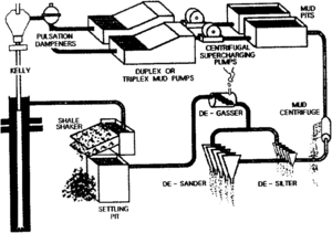
Drilling fluid is circulated by the mud pumps (34 in Figure 1). The volume of mud being pumped is measured by the stroke counters, and the rate of movement is recorded by the stand pipe pressure. The stand pipe connects the mud pumps to the kelly hose. The kelly hose is connected to the swivel (6) on top of the kelly. Mud is pumped down the drill string through the bit and up the annulus or “back side” (the space between the drill pipe and the borehole). Returning mud flows down the flowline (24) into a surge tank (possum belly) and across the shale shakers (25). Shale shakers are vibrating screening devices that are designed to shake so as to separate out the drill cuttings from the mud. The shale shakers are the first place that drill cuttings can be examined and where the gas is extracted from the mud (27 and 28) (Figure 2). After going through the shale shakers the mud passes through a series of tanks or pits where the finer solids are removed via desanders (32), desilters (31) and centrifuges (33), and the mud properties are adjusted. Pits are named for their function (e.g., shale pit, settling pit, volume pit, mixing pit, and suction pit). The mud pumps are charged from the suction pit. Excess mud can also be diverted from the metal mud pits into a large, plastic lined reserve pit (29) located to the side of the rig.
Control and measurement system[edit]
The blowout preventers (BOPs) (38 in Figure 1) are the major component of the control system on a rig, and they are the last line of defence against a blowout. The BOPs are bolted to the wellhead and are not removed until the well is completed and production equipment is installed. BOPs usually have at least four sections:
- Annulars are large, hard rubber slips that fit around any sized pipe. The size flexibility, however, is at the expense of the pressure rating.
- Pipe rams are metal donut-shaped sealing mechanisms that fit only a specific sized pipe but at a high pressure rating.
- Blind or shear rams are edged high-carbon steel sealing mechanisms that can cut pipe and close the hole completely.
- Crossover spools are metal junctions where the choke and kill lines attach.
Additional control equipment includes the kill line, choke line, and flare line. The kill line is used to pump mud into the annulus at the crossover spool in the event that heavier mud is needed to control wellbore pressures. The choke line also helps control wellbore pressures by allowing drilling mud to circulate through a choke manifold (26) (which is a set of backpressure valves). The mud and gas can then be sent down the flare line for disposal or burning in the reserve pit (29).
Monitoring and measurement of the basic functions of the rig are usually made from the driller's console (17) located on the derrick floor. From this console, the driller can monitor equipment, distribute power, change gears, and oversee crew activities. Additional measurement equipment and records are located in the dog house (18) or service shed. The dog house is located to the side of the rig floor and contains the geolograph, a device that makes a time-based chart record of several rig functions, including the following:
- Kelly height or rate of penetration (ROP) (in ft/hr, m/hr, or min/ft)
- Depth (in ft or m)
- Pump pressure (in psi)
- String weight (in thousands of lb)
- Rotary speed (in rpm)
- Rotary torque (in ft-lb)
- Stroke rate (in strokes/min)
- Circulation rate (in gal/min)
See also[edit]
References[edit]
- ↑ Whittaker, A., ed., 1985, Field geologists training guide: Boston, MA, IHRDC, 291 p.

