Search results
Jump to navigation
Jump to search
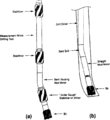
File:Wellbore-trajectory fig6.png (a) Steerable bottom hole assembly, (b) Kicking off with a bent sub and straight mud motor.(890 × 974 (33 KB)) - 21:19, 14 January 2014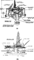
File:Offshore-rigs fig3.png Semisubmersible rigs, (a) Pontoon type semisubmersible. (b) Twin hull semisubmersible. (From Whittaker, 1985.)(942 × 1,663 (39 KB)) - 17:16, 14 January 2014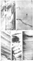
File:M31F27.jpg ...its. ote the lack of disturbance in these deposits. Coleman, J. M., and D. B. Prior, 1981, Deltaic environments of deposition ''in'' P. A. Scholle and D(760 × 1,372 (583 KB)) - 18:23, 18 August 2014
File:Using-and-improving-surface-models-built-by-computer fig8.png Cross sections showing that surfaces that intersect due to (a) baselap or (b) truncation will incorrectly cross one another.(837 × 343 (9 KB)) - 22:32, 13 January 2014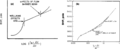
File:Pressure-transient-testing fig5.png (a) Typical buildup curve shape with flow barrier, (b) Doubling of slope on Horner plot for well near barrier.(1,955 × 806 (48 KB)) - 18:23, 14 January 2014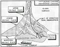
File:M31F1.jpg ...tem. From Deltaic environments of deposition, 1981, Coleman, J. M., and D. B. Prior, in AAPG Memoir 31.(744 × 591 (256 KB)) - 18:15, 15 August 2014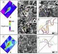
File:AlHawajAlQahtaniFigure6.jpg ...7] A) Faulted horizon surface. The small black box is the location of B-E. B-D) Channels lateral geometry on different horizon levels. E) Restoration us(468 × 439 (80 KB)) - 21:05, 8 November 2021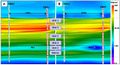
File:AlsaudKatterbauerFigure5.jpg ...se EM resistivity image between OBS1 and OBS2. (A) before water injection (B) After four months of water injection(624 × 338 (79 KB)) - 22:14, 3 February 2022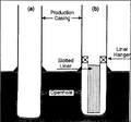
File:Well-completions fig1.png Wellbore diagram of (a) an open hole completion and (b) a slotted liner completion.(947 × 882 (40 KB)) - 21:20, 14 January 2014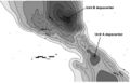
File:Mth14ch02f07.jpg ...depositional accumulations, an interpretation consistent with Units A and B representing separate compartments with different oil-water contacts. From(700 × 449 (53 KB)) - 19:56, 4 December 2015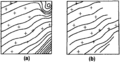
File:Using-and-improving-surface-models-built-by-computer fig1.png ...he same surface data. (a) Unconstrained extrapolation into nondata areas. (b) Contours constrained to areas near data.(923 × 479 (31 KB)) - 22:32, 13 January 2014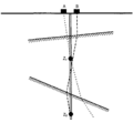
File:Checkshots-and-vertical-seismic-profiles fig3.png The source position (A or B) should be chosen so that the travel path to each receiver is as nearly ver(945 × 875 (8 KB)) - 21:28, 13 January 2014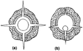
File:Well-completions fig10.png Qualitative description of perforations using (a) a casing gun and (b) a thru-tubing gun.(901 × 556 (29 KB)) - 21:20, 14 January 2014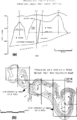
File:Subsurface-maps fig4.png (a) Cross section and (b) net pay Isopach map of the Strachan gas field, western Canada. Contour Int(890 × 1,386 (78 KB)) - 20:42, 14 January 2014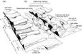
File:AlHawajAlQahtaniFigure5.jpg Schematic 3D geometry of salt structures rising from a) line sources and b) point sources. Note the complexity in all directions resulting from salt d(475 × 311 (57 KB)) - 21:01, 8 November 2021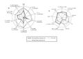
File:AlfraihAlSaifFigure7.jpg A spider diagram illustrating source parameters. A) Aliphatic hydrocarbons, b) aromatic hydrocarbons from oil inclusions and crude oil.(2,100 × 1,500 (487 KB)) - 19:15, 31 January 2022
File:M114CH01FG02.jpg Generalized pre-Mesozoic stratigraphic column for (A) northwest and (B) east-central Saudi Arabian Basin. From AAPG Memoir 114: Petroleum Systems(700 × 619 (117 KB)) - 19:52, 31 December 2018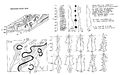
File:M31F4.jpg ...its. From Deltaic environments of deposition, 1981, Coleman, J. M., and D. B. Prior, in AAPG Memoir 31.(1,464 × 916 (326 KB)) - 19:19, 15 August 2014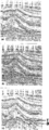
File:Three-dimensional-seismic-method fig1.png {{copyright|a marine 3-D survey. (b) The corresponding 2-D migrated section. (c) The 3-D migrated section. (Dat (a) A CMP-stacked section. Copyright: a marine 3-D survey. (b) The corresponding 2-D migrated section. (c) The 3-D migrated section. (Dat(943 × 2,518 (143 KB)) - 19:36, 14 January 2014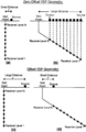
File:Checkshots-and-vertical-seismic-profiles fig4.png Examples of the source-receiver positions involved in (a and b) zero offset and (c and d) offset VSP recording geometries.(942 × 1,445 (56 KB)) - 21:29, 13 January 2014


