Search results
Jump to navigation
Jump to search
Page title matches
File:Seismic-data-acquisition-on-land fig2.png (1,006 × 660 (512 KB)) - 16:15, 14 January 2014
File:Seismic-data-acquisition-on-land fig3.png (1,005 × 659 (599 KB)) - 16:15, 14 January 2014
File:Seismic-data-acquisition-on-land fig4.png (754 × 583 (8 KB)) - 16:15, 14 January 2014
File:Seismic-data-acquisition-on-land fig5.png (1,669 × 506 (9 KB)) - 16:16, 14 January 2014
File:Seismic-data-acquisition-on-land fig6.png (1,004 × 657 (552 KB)) - 16:16, 14 January 2014
File:Seismic-data-acquisition-on-land fig1.png (1,008 × 662 (615 KB)) - 16:15, 14 January 2014


Page text matches
File:Forward-modeling-of-seismic-data fig1.png (1,946 × 1,028 (96 KB)) - 14:35, 14 January 2014
File:Log-analysis-applications fig6.png (894 × 762 (37 KB)) - 16:36, 14 January 2014
File:Figure5MancosCommRept.jpg (1,320 × 556 (175 KB)) - 20:52, 14 April 2021
File:Mapping-with-two-dimensional-seismic-data fig3.png (885 × 1,087 (41 KB)) - 19:36, 14 January 2014
File:BasinCenteredGasFig6.jpg (700 × 442 (70 KB)) - 18:53, 14 January 2015
File:DiapirDiagram.JPG (800 × 870 (270 KB)) - 17:59, 2 January 2015
File:Mapping-with-two-dimensional-seismic-data fig2.png (939 × 644 (47 KB)) - 19:36, 14 January 2014
File:MaiPageBrokenConcretion22.jpg (600 × 600 (180 KB)) - 15:39, 27 July 2015
File:Fundamentals-of-fluid-flow fig7.png (942 × 453 (24 KB)) - 01:52, 14 January 2014
File:MainPageChallaco.jpg (1,201 × 1,200 (469 KB)) - 15:37, 27 July 2015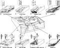
File:Lithofacies-and-environmental-analysis-of-clastic-depositional-systems fig3.png (1,950 × 1,563 (201 KB)) - 21:37, 13 January 2014
File:AlfraihAlSaifFigure3.jpg (931 × 983 (94 KB)) - 19:11, 31 January 2022
File:Production-histories fig4.png (951 × 686 (9 KB)) - 17:29, 14 January 2014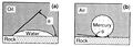
File:Charles-l-vavra-john-g-kaldi-robert-m-sneider capillary-pressure 1.jpg (1,200 × 434 (272 KB)) - 17:41, 13 September 2013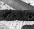
File:Production-problems fig3.png (1,006 × 836 (738 KB)) - 17:29, 14 January 2014
File:Borehole-imaging-devices fig2.png (1,000 × 959 (576 KB)) - 18:53, 13 January 2014
File:Capillary-pressure fig1.png (941 × 333 (26 KB)) - 18:22, 14 January 2014
File:Production-problems fig2.png (925 × 674 (24 KB)) - 17:29, 14 January 2014
File:Dipmeters fig4.png (952 × 2,099 (121 KB)) - 01:19, 14 January 2014
File:Oilfield-water-analysis fig2.png (948 × 990 (16 KB)) - 17:24, 14 January 2014
File:Mth14ch00f02.jpg (500 × 342 (32 KB)) - 21:24, 3 December 2015
File:Magnetics fig1.png (2,677 × 1,649 (34 KB)) - 23:17, 14 January 2014
File:Stimulation fig6.png (941 × 115 (6 KB)) - 20:37, 14 January 2014
File:Permeability fig3.png (939 × 527 (10 KB)) - 18:02, 14 January 2014
File:Box core32.jpg (800 × 600 (63 KB)) - 20:50, 30 June 2014
File:Dipmeters fig6.png (1,738 × 1,203 (88 KB)) - 01:19, 14 January 2014
File:H4CH12FG11.JPG (600 × 322 (73 KB)) - 21:40, 13 July 2015
File:Sedimentary-basin-analysis fig4-55.png (1,660 × 1,158 (586 KB)) - 18:53, 30 January 2014
File:2.png (376 × 491 (118 KB)) - 16:48, 26 June 2015
File:Waterflooding fig5.png (940 × 779 (22 KB)) - 19:18, 14 January 2014
File:Pressure-transient-testing fig7.png (937 × 573 (43 KB)) - 18:23, 14 January 2014
File:AlfraihAlSaifFigure2.jpg (1,436 × 397 (70 KB)) - 19:10, 31 January 2022
File:MainPage AAPGBullFeb2013ZengFigure4.jpg (400 × 400 (68 KB)) - 17:19, 5 January 2015
File:Challaco fluvial deposits - zeesstof via flickr.jpg (3,264 × 2,448 (1.93 MB)) - 20:43, 31 July 2014
File:Evaluating-diagenetically-complex-reservoirs fig4.png (1,980 × 1,622 (338 KB)) - 18:46, 14 January 2014
File:Mth14ch07f04.jpg (500 × 258 (39 KB)) - 17:58, 7 December 2015
File:Uncertainties-impacting-reserves-revenue-and-costs fig1.png (891 × 605 (29 KB)) - 19:20, 14 January 2014
File:Uncertainties-impacting-reserves-revenue-and-costs fig2.png (1,966 × 2,657 (229 KB)) - 19:20, 14 January 2014
File:Mth14ch04f06.jpg (800 × 563 (141 KB)) - 16:55, 7 December 2015
File:Borehole-imaging-devices fig7.png (1,008 × 934 (508 KB)) - 18:53, 13 January 2014
File:M114CH03FG01.jpg (691 × 944 (147 KB)) - 17:46, 4 January 2019
File:Pressure-transient-testing fig5.png (1,955 × 806 (48 KB)) - 18:23, 14 January 2014
File:Conducting-a-reservoir-simulation-study-an-overview fig3.png (926 × 1,188 (30 KB)) - 18:46, 14 January 2014
File:Production-logging fig7.png (932 × 1,229 (49 KB)) - 16:37, 14 January 2014
File:AlHawajAlQahtaniFigure6.jpg (468 × 439 (80 KB)) - 21:05, 8 November 2021
File:Introduction-to-contouring-geological-data-with-a-computer fig4.png (942 × 1,209 (53 KB)) - 22:06, 13 January 2014
File:Fluid-contacts fig1.png (1,932 × 1,198 (79 KB)) - 01:51, 14 January 2014
File:1.png (398 × 552 (187 KB)) - 16:45, 26 June 2015
File:Mth14ch02f01.jpg (700 × 457 (103 KB)) - 23:18, 3 December 2015
File:Drill-stem-testing fig5.png (757 × 558 (5 KB)) - 22:25, 14 January 2014
File:Sem-xrd-cl-and-xf-methods fig4.png (919 × 909 (13 KB)) - 22:29, 14 January 2014
File:M91Ch6FG40.JPG (600 × 402 (45 KB)) - 16:55, 3 June 2015
File:Thin-section-analysis fig1.png (933 × 870 (15 KB)) - 21:07, 14 January 2014
File:M115CH02FG01.jpg (700 × 480 (92 KB)) - 19:31, 10 January 2019
File:South Africa-Eastern Cape-Gamtoos Valley-Alluvial Gravel01.jpg (800 × 533 (118 KB)) - 15:41, 5 July 2016
File:M91FG197.JPG (800 × 755 (66 KB)) - 13:09, 20 August 2015
File:Using-and-improving-surface-models-built-by-computer fig24.png (878 × 508 (15 KB)) - 22:33, 13 January 2014
File:M115CH11FG01.jpg (1,284 × 862 (908 KB)) - 15:10, 22 January 2019
File:Introduction-to-contouring-geological-data-with-a-computer fig7.png (940 × 1,218 (51 KB)) - 22:06, 13 January 2014
File:Waterflooding fig6.png (944 × 1,299 (15 KB)) - 19:18, 14 January 2014
File:Using-and-improving-surface-models-built-by-computer fig14.png (871 × 572 (15 KB)) - 22:32, 13 January 2014
File:Systems Tracts.jpg (750 × 386 (174 KB)) - 20:29, 21 July 2014
File:AlHawajAlQahtaniFigure4.jpg (468 × 361 (57 KB)) - 21:00, 8 November 2021
File:Surface-geochemical-exploration-for-petroleum fig18-5.png (1,678 × 951 (482 KB)) - 18:30, 18 January 2014
File:Oil-and-condensate-analysis fig6.png (1,915 × 761 (52 KB)) - 17:17, 14 January 2014
File:NileDelta.jpg (689 × 700 (161 KB)) - 18:06, 15 August 2014
File:M91FG171.JPG (800 × 734 (138 KB)) - 17:18, 29 July 2015
File:MainPageNileDelta.jpg (390 × 400 (166 KB)) - 19:55, 6 April 2015
File:Mth14ch00f01.jpg (500 × 277 (35 KB)) - 23:19, 23 November 2015
File:M31F3.jpg (2,941 × 1,884 (830 KB)) - 19:02, 15 August 2014
File:M91FG195.JPG (800 × 669 (93 KB)) - 15:36, 17 August 2015
File:AlHawajAlQahtaniFigure1.jpg (979 × 447 (95 KB)) - 20:44, 8 November 2021
File:ST53 Part01 Pg08D.jpg (750 × 405 (164 KB)) - 20:39, 27 July 2015
File:M115CH11FG10.jpg (1,214 × 1,325 (406 KB)) - 15:28, 22 January 2019
File:Correlation-and-regression-analysis fig1.png (942 × 598 (16 KB)) - 18:39, 14 January 2014
File:Log-analysis-applications fig7.png (925 × 838 (28 KB)) - 16:36, 14 January 2014
File:M91FG191.JPG (800 × 873 (118 KB)) - 21:14, 12 August 2015
File:M115CH02FG06.jpg (700 × 255 (74 KB)) - 21:53, 10 January 2019
File:MainPageFG18CoreSt63Appendix3.jpg (400 × 400 (104 KB)) - 16:14, 29 June 2015
File:M91Ch13FG91.JPG (600 × 736 (137 KB)) - 21:40, 29 April 2015
File:Drill-stem-testing fig7.png (728 × 559 (6 KB)) - 22:25, 14 January 2014
File:M91Ch11FG70.JPG (600 × 353 (134 KB)) - 15:46, 27 April 2015
File:Log-analysis-applications fig2.png (939 × 983 (9 KB)) - 16:36, 14 January 2014
File:M115CH02FG04.jpg (700 × 662 (290 KB)) - 21:44, 10 January 2019
File:Mapping-with-two-dimensional-seismic-data fig6.png (909 × 1,853 (102 KB)) - 19:36, 14 January 2014
File:Mapping-with-two-dimensional-seismic-data fig1.png (945 × 749 (19 KB)) - 19:36, 14 January 2014
File:Using-and-improving-surface-models-built-by-computer fig18.png (835 × 790 (37 KB)) - 22:32, 13 January 2014
File:M31F25.jpg (1,087 × 1,348 (940 KB)) - 18:21, 18 August 2014
File:Evaluating-tight-gas-reservoirs fig1.png (1,937 × 1,409 (50 KB)) - 18:47, 14 January 2014
File:Seal capacity trap type fig1.png (2,000 × 1,329 (731 KB)) - 17:49, 6 February 2014
File:Seal capacity trap type fig2.png (2,000 × 1,327 (803 KB)) - 17:50, 6 February 2014
File:M31F29.jpg (1,161 × 1,502 (970 KB)) - 18:25, 18 August 2014
File:M91FG112.JPG (800 × 856 (118 KB)) - 19:29, 18 August 2015
File:M115CH11FG04.jpg (1,277 × 860 (520 KB)) - 15:21, 22 January 2019
File:Mem91BuoyanceForcesFig27.jpg (600 × 852 (64 KB)) - 17:18, 7 April 2014
File:M115CH02FG05.jpg (2,917 × 2,758 (906 KB)) - 21:50, 10 January 2019
File:Thin-section-analysis fig2.png (1,959 × 1,366 (182 KB)) - 21:07, 14 January 2014
File:Drill-stem-testing fig8.png (755 × 573 (6 KB)) - 22:25, 14 January 2014
File:AAPGBullFeb2013ZengFigure4.JPG (800 × 613 (224 KB)) - 18:22, 30 June 2014
File:M115CH10FG04.jpg (1,266 × 845 (845 KB)) - 18:43, 17 January 2019
File:BasinCenteredGasFig7.jpg (700 × 392 (40 KB)) - 18:58, 14 January 2015
File:Using-and-improving-surface-models-built-by-computer fig13.png (926 × 1,096 (55 KB)) - 22:32, 13 January 2014
File:BasinCenteredGasFig9.jpg (500 × 475 (43 KB)) - 19:16, 14 January 2015
File:BasinCenteredGasFig8.jpg (700 × 389 (41 KB)) - 19:13, 14 January 2015
File:Core-description fig1.png (1,879 × 2,521 (232 KB)) - 22:38, 13 January 2014
File:M115CH10FG03.jpg (1,076 × 597 (435 KB)) - 18:42, 17 January 2019
File:M91FG174.JPG (800 × 639 (117 KB)) - 16:13, 31 July 2015
File:M91Ch13FG80.JPG (800 × 660 (102 KB)) - 21:14, 29 April 2015
File:M91FG186.JPG (800 × 1,137 (157 KB)) - 19:22, 13 August 2015
File:M114CH03FG02.jpg (700 × 930 (155 KB)) - 17:48, 4 January 2019
File:M91FG199.JPG (800 × 1,089 (126 KB)) - 13:11, 20 August 2015
File:BasinCenteredGasFig4.jpg (600 × 783 (79 KB)) - 22:22, 13 January 2015
File:M91Ch06FG44.JPG (800 × 696 (58 KB)) - 17:11, 3 June 2015
File:M31F2.jpg (365 × 772 (175 KB)) - 18:56, 15 August 2014
File:GumelarFigure4.jpg (652 × 468 (90 KB)) - 21:13, 28 September 2021
File:M114CH08FG02.jpg (700 × 381 (50 KB)) - 18:09, 7 January 2019
File:Mth14ch04f04.jpg (400 × 202 (17 KB)) - 16:51, 7 December 2015
File:Mth14ch07f02.jpg (500 × 923 (106 KB)) - 17:50, 7 December 2015
File:Mth14ch04f03.jpg (500 × 495 (47 KB)) - 16:09, 7 December 2015
File:M98Ch3Fig2.JPG (600 × 898 (278 KB)) - 16:31, 19 August 2014
File:M106Ch07Fig04.jpg (564 × 855 (75 KB)) - 20:49, 18 April 2016
File:Mth14ch02f03.jpg (700 × 529 (75 KB)) - 15:26, 4 December 2015
File:Mth14ch02f06.jpg (700 × 481 (51 KB)) - 17:48, 4 December 2015
File:Evaluating-structurally-complex-reservoirs fig7.png (861 × 1,502 (31 KB)) - 18:47, 14 January 2014
File:Charles-l-vavra-john-g-kaldi-robert-m-sneider capillary-pressure 5.jpg (1,200 × 670 (154 KB)) - 17:42, 13 September 2013
File:Capillary-pressure fig5.png (1,805 × 1,011 (101 KB)) - 18:22, 14 January 2014
File:FG11.JPG (800 × 648 (291 KB)) - 15:04, 5 August 2014
File:Flow-units-for-reservoir-characterization fig1.png (1,487 × 976 (91 KB)) - 23:13, 14 January 2014
File:Mth14ch07f05.jpg (500 × 264 (41 KB)) - 18:09, 7 December 2015
File:Mth14ch04f05.jpg (700 × 469 (63 KB)) - 16:53, 7 December 2015
File:Mth14ch02f04.jpg (500 × 605 (114 KB)) - 15:58, 4 December 2015
File:Evaluating-structurally-complex-reservoirs fig4.png (951 × 915 (46 KB)) - 18:47, 14 January 2014
File:Mth14ch02f07.jpg (700 × 449 (53 KB)) - 19:56, 4 December 2015
File:Mth14ch04f01.jpg (700 × 525 (111 KB)) - 16:00, 7 December 2015
File:Mth14ch02f05.jpg (500 × 682 (64 KB)) - 17:07, 4 December 2015
File:Mthch02f02.jpg (300 × 453 (36 KB)) - 15:19, 4 December 2015
File:Mth14ch02f09.jpg (600 × 541 (60 KB)) - 20:21, 4 December 2015
File:Fluid-contacts fig4.png (1,924 × 933 (108 KB)) - 01:52, 14 January 2014
File:Mth14ch07f03.jpg (700 × 409 (77 KB)) - 17:55, 7 December 2015
File:H4CH12FG7.JPG (600 × 599 (51 KB)) - 21:12, 9 July 2015
File:Mth14ch07f01.jpg (700 × 809 (135 KB)) - 17:34, 7 December 2015
File:Mth14ch04f02.jpg (500 × 718 (88 KB)) - 16:08, 7 December 2015
File:Mth14ch02f08.jpg (400 × 465 (28 KB)) - 20:19, 4 December 2015
File:M98Ch3Fig3.JPG (600 × 743 (211 KB)) - 16:39, 19 August 2014
File:H4CH12FG6.JPG (600 × 611 (85 KB)) - 21:07, 9 July 2015
File:M98Ch3Fig5.JPG (600 × 674 (275 KB)) - 16:53, 19 August 2014
File:NacratonUSGS.jpg (512 × 599 (332 KB)) - 15:27, 19 August 2014
File:M115CH02FG03.jpg (700 × 767 (157 KB)) - 21:29, 10 January 2019


