Search results
Jump to navigation
Jump to search
Page title matches

File:Platform A Dos Cuadras.jpg (300 × 200 (23 KB)) - 16:18, 15 January 2014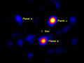
File:444226main exoplanet20100414-a-full.jpg (1,024 × 768 (47 KB)) - 19:48, 26 January 2016
File:A-development-geology-workstation fig1.png Principal components of a development geology workstation.(1,913 × 1,312 (134 KB)) - 15:34, 14 January 2014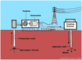
File:Simplified diagram of a geotermal plant.png (378 × 276 (96 KB)) - 16:47, 24 June 2015
File:Developing-a-philosophy-of-exploration fig1-1.png (1,979 × 704 (257 KB)) - 16:38, 30 January 2014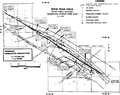
File:Developing-a-philosophy-of-exploration fig1-2.png (1,731 × 1,366 (443 KB)) - 16:41, 30 January 2014
File:Developing-a-philosophy-of-exploration fig1-3.png (1,681 × 847 (80 KB)) - 16:42, 30 January 2014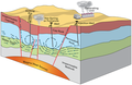
File:Simplified diagram of a geotermal power plant.png (373 × 243 (69 KB)) - 16:46, 24 June 2015
File:Conducting-a-reservoir-simulation-study-an-overview fig3.png (926 × 1,188 (30 KB)) - 18:46, 14 January 2014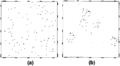
File:Introduction-to-contouring-geological-data-with-a-computer fig1.png (a) Random points. (b) Clustered points.(947 × 524 (13 KB)) - 22:06, 13 January 2014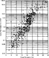
File:Conducting-a-reservoir-simulation-study-an-overview fig4.png (926 × 1,100 (24 KB)) - 18:46, 14 January 2014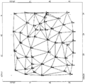
File:Introduction-to-contouring-geological-data-with-a-computer fig2.png (942 × 932 (23 KB)) - 22:06, 13 January 2014
File:Conducting-a-reservoir-simulation-study-an-overview fig5.png (854 × 1,328 (69 KB)) - 18:46, 14 January 2014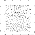
File:Introduction-to-contouring-geological-data-with-a-computer fig3.png (948 × 938 (21 KB)) - 22:06, 13 January 2014
File:Conducting-a-reservoir-simulation-study-an-overview fig6.png (931 × 813 (29 KB)) - 18:46, 14 January 2014
File:Introduction-to-contouring-geological-data-with-a-computer fig4.png Surface contoured on a triangular mesh. The original surface is a fourth-order polynomial.(942 × 1,209 (53 KB)) - 22:06, 13 January 2014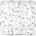
File:Introduction-to-contouring-geological-data-with-a-computer fig5.png Contours from a 13 × 13 grid using nearest neighbor search. (Data from Davis, 1973.)(943 × 946 (63 KB)) - 22:06, 13 January 2014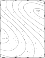
File:Introduction-to-contouring-geological-data-with-a-computer fig7.png ...the fourth-order polynomial of Figure 4 contoured on a grid prepared using a nearest neighbor search criterion.(940 × 1,218 (51 KB)) - 22:06, 13 January 2014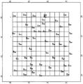
File:Introduction-to-contouring-geological-data-with-a-computer fig6.png (947 × 957 (42 KB)) - 22:06, 13 January 2014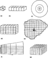
File:Conducting-a-reservoir-simulation-study-an-overview fig1.png Typical models used in reservoir simulation. (a) Zero-dimensional tank. (b) One-dimensional linear. (c) One-dimensional rad(922 × 1,118 (50 KB)) - 18:46, 14 January 2014


Page text matches
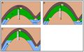
File:GumelarFigure8.jpg ...leaks from a major structure. HCH in a) has a lower height than b). c) has a spill point value that is above the crest depth so that no leakage occurs ((870 × 540 (75 KB)) - 20:33, 28 October 2021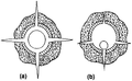
File:Well-completions fig10.png Qualitative description of perforations using (a) a casing gun and (b) a thru-tubing gun.(901 × 556 (29 KB)) - 21:20, 14 January 2014File:Introduction-to-contouring-geological-data-with-a-computer fig7.png ...the fourth-order polynomial of Figure 4 contoured on a grid prepared using a nearest neighbor search criterion.(940 × 1,218 (51 KB)) - 22:06, 13 January 2014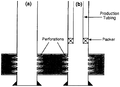
File:Well-completions fig3.png Wellbore diagram of (a) a perforated completion and (b) a single completion inside perforated casing.(940 × 683 (34 KB)) - 21:20, 14 January 2014
File:M91Ch13FG82.JPG ...drilled through a reverse fault or with a highly deviated well penetrating a normal fault. From Shepherd, M., 2009, Structural geology: Faults, in M. Sh(600 × 820 (92 KB)) - 21:16, 29 April 2015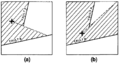
File:Using-and-improving-surface-models-built-by-computer fig15.png ...data in the hatchured area. (b) A grid node farther to the south of fault A can see more data, thus the surface smoothly changes form around the fault(926 × 491 (27 KB)) - 22:32, 13 January 2014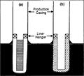
File:Well-completions fig2.png Wellbore diagram of (a) a screen and liner completion and (b) a cement liner completion.(946 × 863 (40 KB)) - 21:20, 14 January 2014
File:Figure-9.jpg ...em captures an image of each newly exposed surface. At right, a picture of a commercial FIB-SEM CrossBeam™ system, Auriga. From AAPG Memoir 102, Chapt(982 × 410 (22 KB)) - 17:35, 15 August 2014
File:Log-analysis-applications fig3.png .... If node values are atypical for a given well due to tool miscalibration, a correct distribution and range can be determined and the trace normalized.(937 × 789 (19 KB)) - 16:36, 14 January 2014
File:Well-completions fig9.png ...ting overbalanced with a casing gun and (b) perforating underbalanced with a thrutubing gun.(1,880 × 1,143 (110 KB)) - 21:20, 14 January 2014
File:M31F2.jpg ...n lenticular sets that form the overlying zone in a fining-upward cycle of a braided channel. C. Ripple drift bedding separated by parallel sand laminat(365 × 772 (175 KB)) - 18:56, 15 August 2014
File:SandPeel.JPG A portion of a wood mounded Sand Peel.(1,280 × 1,280 (984 KB)) - 21:30, 3 July 2014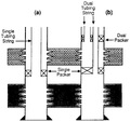
File:Well-completions fig4.png Wellbore diagram of (a) a casing-tubing dual completion and (b) a completion with dual packers and dual tubing strings.(953 × 901 (48 KB)) - 21:20, 14 January 2014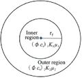
File:AlAhmadiTawfiqFigure8.jpg Schematic of a Two Region Radial Composite Reservoir (H., Li, L., & Mu, A. 2018).(312 × 297 (17 KB)) - 23:12, 9 November 2021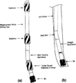
File:Wellbore-trajectory fig6.png (a) Steerable bottom hole assembly, (b) Kicking off with a bent sub and straight mud motor.(890 × 974 (33 KB)) - 21:19, 14 January 2014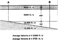
File:Mapping-with-two-dimensional-seismic-data fig2.png ...cled lines constitute a group having small misties. A group can be used as a base to which times on all other lines are adjusted. For example, times on(939 × 644 (47 KB)) - 19:36, 14 January 2014
File:Evaluating-structurally-complex-reservoirs fig5.png Example of a balanced section through a complex thrust ramp structure showing both the deformed and undeformed sect(2,720 × 1,344 (81 KB)) - 18:47, 14 January 2014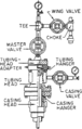
File:Surface-production-equipment fig1.png Typical wellhead for a flowing well with a single-wing, single-completion threaded manifold.(837 × 1,312 (76 KB)) - 17:29, 14 January 2014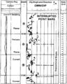
File:Dipmeters fig7.png Field example of a detailed dip computation through a sequence of interrupted meandering stream point bars.(955 × 1,189 (73 KB)) - 01:19, 14 January 2014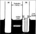
File:Well-completions fig1.png Wellbore diagram of (a) an open hole completion and (b) a slotted liner completion.(947 × 882 (40 KB)) - 21:20, 14 January 2014


