Search results
Jump to navigation
Jump to search
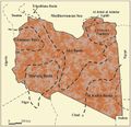
File:M106Ch04Fig03.jpg ...4, Hydrocarbon provinces of Libya: A petroleum system study, in L. Marlow, C. Kendall, and L. Yose, eds., Petroleum systems of the Tethyan region: AAPG(700 × 676 (77 KB)) - 20:13, 28 March 2016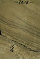
File:FG18CoreSt63Appendix3.JPG Core slab photo. From Ruppel, Stephen C., 2012, Appendix 3, in S. C. Ruppel, ed., Anatomy of a giant carbonate reservoir: Fullerton Clear Fork(600 × 890 (315 KB)) - 16:10, 29 June 2015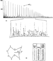
File:Oil-and-condensate-analysis fig5.png ...for peaks between <italic>n</italic>-C<sub>17</sub> and <italic>n</italic>-C<sub>25</sub>.(1,942 × 2,226 (120 KB)) - 17:17, 14 January 2014
File:M106Ch04Fig04.jpg ...4, Hydrocarbon provinces of Libya: A petroleum system study, in L. Marlow, C. Kendall, and L. Yose, eds., Petroleum systems of the Tethyan region: AAPG(700 × 383 (50 KB)) - 20:18, 28 March 2016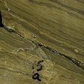
File:MainPageFG18CoreSt63Appendix3.jpg Core slab photo. From Ruppel, Stephen C., 2012, Appendix 3, in S. C. Ruppel, ed., Anatomy of a giant carbonate reservoir: Fullerton Clear Fork(400 × 400 (104 KB)) - 16:14, 29 June 2015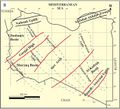
File:M106Ch04Fig2B.jpg ...4, Hydrocarbon provinces of Libya: A petroleum system study, in L. Marlow, C. Kendall, and L. Yose, eds., Petroleum systems of the Tethyan region: AAPG(700 × 635 (73 KB)) - 19:43, 28 March 2016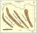
File:M106Ch04Fig2A.jpg ...4, Hydrocarbon provinces of Libya: A petroleum system study, in L. Marlow, C. Kendall, and L. Yose, eds., Petroleum systems of the Tethyan region: AAPG(700 × 633 (66 KB)) - 19:44, 28 March 2016
File:Conventional-coring fig1.png {{copyright|Eastman Christensen, Technical Data Sheet C-105}} ...entional core barrel. Copyright: Eastman Christensen, Technical Data Sheet C-105.(542 × 2,088 (59 KB)) - 22:37, 13 January 2014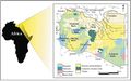
File:M106h04Fig01.jpg ...l, Hydrocarbon provinces of Libya: A petroleum system study, in L. Marlow, C. Kendall, and L. Yose, eds., Petroleum systems of the Tethyan region: AAPG(700 × 439 (50 KB)) - 19:01, 28 March 2016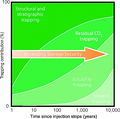
File:CO2TrappingMechanisms.JPG ...to selection and evaluation of CO2 geosequestration sites, in M. Grobe, J. C. Pashin, and R. L. Dodge, eds., Carbon dioxide sequestration in geological(600 × 596 (131 KB)) - 18:25, 7 August 2014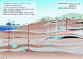
File:CO2StorageOptions.JPG ...to selection and evaluation of CO2 geosequestration sites, in M. Grobe, J. C. Pashin, and R. L. Dodge, eds., Carbon dioxide sequestration in geological(800 × 570 (244 KB)) - 17:26, 7 August 2014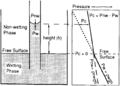
File:Capillary-pressure fig2.png ...ce in pressure measured across the interface in the capillary (''P''<sub>''c''</sub> = ''P''<sub>nw</sub> – P<sub>w</sub>). This pressure results from(947 × 675 (25 KB)) - 18:22, 14 January 2014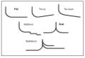
File:Mth14ch00f02.jpg ...ntal Wells: Focus on the Reservoir, Edited by T. R. Carr, E. P. Mason, and C. T. Feazel.(500 × 342 (32 KB)) - 21:24, 3 December 2015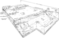
File:Carbonate-reservoir-models-facies-diagenesis-and-flow-characterization fig2.png Carbonate depositional environments. (Diagram by R. G. Loucks and C. R. Handford, unpublished.)(2,773 × 1,788 (136 KB)) - 19:02, 13 January 2014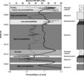
File:Mth14ch02f09.jpg ...ntal Wells: Focus on the Reservoir, Edited by T. R. Carr, E. P. Mason, and C. T. Feazel.(600 × 541 (60 KB)) - 20:21, 4 December 2015
File:Three-dimensional-seismic-method fig1.png {{copyright|a marine 3-D survey. (b) The corresponding 2-D migrated section. (c) The 3-D migrated section. (Data courtesy of Amoco Europe and West Africa, ...pyright: a marine 3-D survey. (b) The corresponding 2-D migrated section. (c) The 3-D migrated section. (Data courtesy of Amoco Europe and West Africa,(943 × 2,518 (143 KB)) - 19:36, 14 January 2014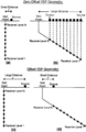
File:Checkshots-and-vertical-seismic-profiles fig4.png ...es of the source-receiver positions involved in (a and b) zero offset and (c and d) offset VSP recording geometries.(942 × 1,445 (56 KB)) - 21:29, 13 January 2014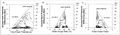
File:GumelarFigure7.jpg ...ng capacity in reservoir (a) Clay Smear Potential; (b) Shale Gouge Ratio; (c) Shale Smear Factor (Yielding et al, 1997).(880 × 256 (64 KB)) - 17:25, 29 September 2021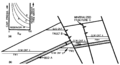
File:Fluid-contacts fig5.png ...en contacts 1 and 3. The displacement pressure of the mineralized fracture C results in the difference in elevation between contacts 3 and 4. The gas co(1,908 × 1,034 (76 KB)) - 01:52, 14 January 2014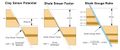
File:GumelarFigure6.jpg ...ears in the fault plane. (a) Potential Clay Smear; (b) Shale Gouge Ratio; (c) Shale Smear Factor (redrawn from Yielding, 1997).(1,347 × 565 (92 KB)) - 17:25, 29 September 2021


