Search results
Jump to navigation
Jump to search
Page title matches
File:UDip Growth Fault Fig 2.png (525 × 363 (98 KB)) - 19:02, 1 July 2015
File:UDip Growth Fault Fig 3.png (582 × 373 (73 KB)) - 19:02, 1 July 2015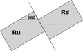
File:Evaluating-top-and-fault-seal fig10-4.png (1,053 × 638 (37 KB)) - 13:33, 31 January 2014
File:Evaluating-top-and-fault-seal fig10-40.png (1,248 × 1,505 (747 KB)) - 15:21, 31 January 2014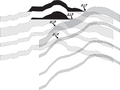
File:Evaluating-top-and-fault-seal fig10-15.png (1,141 × 853 (78 KB)) - 13:49, 31 January 2014
File:Evaluating-top-and-fault-seal fig10-51.png (783 × 1,361 (611 KB)) - 15:37, 31 January 2014
File:Evaluating-top-and-fault-seal fig10-29.png (1,681 × 720 (1.43 MB)) - 14:05, 31 January 2014
File:Evaluating-top-and-fault-seal fig10-5.png (838 × 497 (16 KB)) - 13:34, 31 January 2014
File:Evaluating-top-and-fault-seal fig10-41.png (1,191 × 750 (353 KB)) - 15:22, 31 January 2014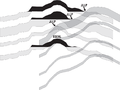
File:Evaluating-top-and-fault-seal fig10-16.png (1,108 × 828 (76 KB)) - 13:50, 31 January 2014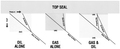
File:Evaluating-top-and-fault-seal fig10-52.png (1,662 × 680 (344 KB)) - 15:39, 31 January 2014
File:Evaluating-top-and-fault-seal fig10-30.png (1,983 × 864 (154 KB)) - 14:07, 31 January 2014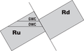
File:Evaluating-top-and-fault-seal fig10-6.png (1,053 × 639 (39 KB)) - 13:36, 31 January 2014
File:Evaluating-top-and-fault-seal fig10-42.png (1,514 × 730 (546 KB)) - 15:24, 31 January 2014
File:Evaluating-top-and-fault-seal fig10-17.png (804 × 1,015 (25 KB)) - 13:51, 31 January 2014
File:Evaluating-top-and-fault-seal fig10-53.png (1,128 × 706 (94 KB)) - 15:41, 31 January 2014
File:Evaluating-top-and-fault-seal fig10-31.png (1,648 × 1,173 (184 KB)) - 14:08, 31 January 2014
File:Evaluating-top-and-fault-seal fig10-7.png (1,054 × 638 (41 KB)) - 13:37, 31 January 2014
File:Evaluating-top-and-fault-seal fig10-43.png (874 × 1,568 (700 KB)) - 15:25, 31 January 2014
File:Evaluating-top-and-fault-seal fig10-18.png (593 × 844 (16 KB)) - 13:53, 31 January 2014


Page text matches
File:GumelarFigure3.jpg ...ors that influence fault analysis: juxtaposition seal, fault rock seal and fault reactivation (Yielding et al, 2010).(700 × 386 (59 KB)) - 20:46, 28 September 2021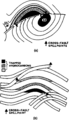
File:Evaluating-structurally-complex-reservoirs fig7.png ...orizons are shown white. Note the effect of thick seal trapping across the fault. (From Allan, 1989.)(861 × 1,502 (31 KB)) - 18:47, 14 January 2014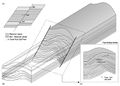
File:GumelarFigure4.jpg ...e fault surface can be complex. (c) Allan's Mapping technique resolves the fault surface into a flat plane and maps the position of the footwall and hanging(652 × 468 (90 KB)) - 21:13, 28 September 2021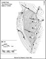
File:M91Ch13FG84.JPG ...uts for the interpreted surface. The downthrown (hanging wall) side of the fault is indicated by a blocked out symbol (from Gluyas and Underhill, 2003). Rep(600 × 766 (134 KB)) - 21:34, 29 April 2015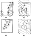
File:Using-and-improving-surface-models-built-by-computer fig13.png ...the block edge. (d) When displayed, contours are constrained to inside the fault block polygon and all models are displayed on the same map. (After Jones et(926 × 1,096 (55 KB)) - 22:32, 13 January 2014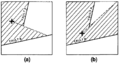
File:Using-and-improving-surface-models-built-by-computer fig15.png ...ult A can see more data, thus the surface smoothly changes form around the fault ends. (After Jones et al., 1986.)(926 × 491 (27 KB)) - 22:32, 13 January 2014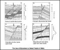
File:M91Ch13FG80.JPG ...resent. Drag patterns may also be seen on the dip data above and below the fault intersection in a well (from Schlumberger, 1981). Courtesy of Schlumberger.(800 × 660 (102 KB)) - 21:14, 29 April 2015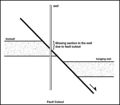
File:M91Ch13FG81.JPG ...tratigraphy in a well penetrating a normal fault will be incomplete due to fault cutout. From Shepherd, M., 2009, Structural geology: Faults, in M. Shepherd(600 × 525 (31 KB)) - 21:15, 29 April 2015
File:ST53 Part01 Pg08B.jpg ...From AAPG Studies in Geology #53: Seismic Interpretation of Contractional Fault-Related Folds, An AAPG Seismic Atlas, edited by John H. Shaw, Christopher D(750 × 607 (183 KB)) - 17:58, 21 July 2015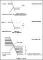
File:M91Ch13FG90.JPG ...t seal analysis involves numerical methods of predicting the likelihood of fault seal (from Yielding et al., 1997). From Shepherd, M., 2009, Structural geol(600 × 823 (51 KB)) - 21:39, 29 April 2015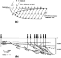
File:Evaluating-structurally-complex-reservoirs fig4.png ...olation between these points is carried out using a half grid spacing. (b) Fault trajectory reconstruction by the Groshong (1989b) method uses simultaneous(951 × 915 (46 KB)) - 18:47, 14 January 2014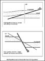
File:M91Ch13FG82.JPG ...hrough a reverse fault or with a highly deviated well penetrating a normal fault. From Shepherd, M., 2009, Structural geology: Faults, in M. Shepherd, Oil f(600 × 820 (92 KB)) - 21:16, 29 April 2015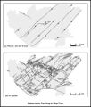
File:M91Ch13FG93.JPG ...surveys at reservoir depths. In map (b), every mapped fault is shown, with fault throws of between 10 cm (4 in.) and 180 m (590 ft) (from Watterson et al.,(600 × 704 (72 KB)) - 21:40, 29 April 2015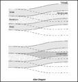
File:M91Ch13FG89.JPG ...oth the hanging wall and footwall blocks of a fault superimposed along the fault plane. At a glance, it can be seen where reservoir and nonreservoir litholo(600 × 632 (54 KB)) - 21:38, 29 April 2015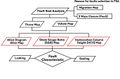
File:GumelarFigure2.jpg Fault seal analysis flowchart.(1,366 × 904 (143 KB)) - 20:38, 28 September 2021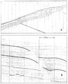
File:M31F25.jpg ...the increased accumulation of sedimentation on the downthrown side of the fault. Horizontal scale is 300 m between shot points and vertical scale is 10 mil(1,087 × 1,348 (940 KB)) - 18:21, 18 August 2014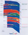
File:Evaluating-top-and-fault-seal fig10-28.jpg [[Category:Evaluating top and fault seal]](1,682 × 2,134 (1.01 MB)) - 16:17, 31 January 2014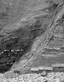
File:Evaluating-top-and-fault-seal fig10-20.jpg [[Category:Evaluating top and fault seal]](1,577 × 2,012 (1.54 MB)) - 16:21, 31 January 2014
File:Evaluating-top-and-fault-seal fig10-24.jpg [[Category:Evaluating top and fault seal]](1,124 × 2,169 (602 KB)) - 16:23, 31 January 2014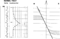
File:Dipmeters fig5.png Simple dip model for the description of a normal fault with drag.(1,745 × 1,150 (71 KB)) - 01:19, 14 January 2014


