Search results
Jump to navigation
Jump to search
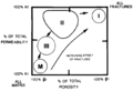
File:Evaluating-fractured-reservoirs fig1.png ...lic>r</italic></sub>= matrix permeability, ϕ<sub><italic>r</italic></sub>= matrix porosity.(942 × 642 (23 KB)) - 15:00, 14 January 2014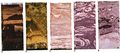
File:M31F14v2.jpg ...he base of the channel. B. Highly contorted and disrupted bedding in sandy matrix in channel-fill deposits. C. Irregular bedding and burrowed structures in s(1,134 × 503 (75 KB)) - 15:16, 18 August 2014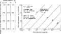
File:Evaluating-fractured-reservoirs fig4.png ...o fractures plotted as a function of fracture width, fracture spacing, and matrix porosity. Copyright: Nelson, 1985</xref>; courtesy of Gulf Publishing Co.(1,929 × 1,078 (31 KB)) - 15:00, 14 January 2014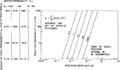
File:Evaluating-fractured-reservoirs fig3.png ...o fractures plotted as a function of fracture width, fracture spacing, and matrix permeability. Copyright: Nelson, 1985</xref>; courtesy of Gulf Publishing C(1,931 × 1,127 (80 KB)) - 15:00, 14 January 2014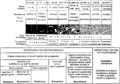
File:Thin-section-analysis fig2.png ...n or thin section. In Folk's scheme, the black pattern represents lime mud matrix, the lined pattern represents sparry calcite cement, and the white objects(1,959 × 1,366 (182 KB)) - 21:07, 14 January 2014


