Search results
Jump to navigation
Jump to search
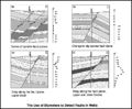
File:M91Ch13FG80.JPG ...can be used to pick likely fault planes in wells. Changes in dip amplitude or azimuth can indicate that a fault is present. Drag patterns may also be see(800 × 660 (102 KB)) - 21:14, 29 April 2015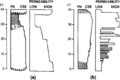
File:Geological-heterogeneities fig2.png ...ermeability profiles of (a) fining- or thinning-upward and (b) coarsening- or thickening-upward sequences. ''Fining'' and ''coarsening'' refer to average(940 × 630 (40 KB)) - 15:35, 14 January 2014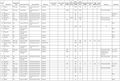
File:M106Ch12Table2b.jpg ...ce strata type: basinal marine (includes calcareous and marly lithologies) or basinal shale. Volumes of oil and gas in-place, estimated ultimate recovera(700 × 474 (70 KB)) - 15:30, 12 May 2016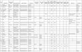
File:M106Ch12Table2.jpg ...ce strata type: basinal marine (includes calcareous and marly lithologies) or basinal shale. Volumes of oil and gas in-place, estimated ultimate recovera(700 × 442 (69 KB)) - 15:28, 12 May 2016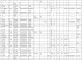
File:M106Ch12Table2a.jpg ...ce strata type: basinal marine (includes calcareous and marly lithologies) or basinal shale. Volumes of oil and gas in-place, estimated ultimate recovera(700 × 515 (83 KB)) - 15:29, 12 May 2016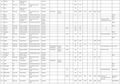
File:M106Ch12Table2c.jpg ...ce strata type: basinal marine (includes calcareous and marly lithologies) or basinal shale. Volumes of oil and gas in-place, estimated ultimate recovera(700 × 489 (73 KB)) - 15:30, 12 May 2016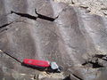
File:1024px-WaveRipple.JPG Wave ripple or symmetric ripple, from Permian rocks in Nomgon, Mongolia. Photo by Matt Aff(1,024 × 768 (251 KB)) - 20:29, 22 December 2014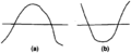
File:Using-and-improving-surface-models-built-by-computer fig8.png Cross sections showing that surfaces that intersect due to (a) baselap or (b) truncation will incorrectly cross one another.(837 × 343 (9 KB)) - 22:32, 13 January 2014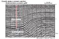
File:ST53 Part01 Pg11A.jpg ...thin toward the structural high. Growth strata are generally folded in one or more limbs of the structure. In this seismic section, growth strata thin on(750 × 509 (230 KB)) - 16:23, 28 July 2015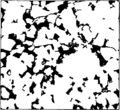
File:Reservoir-quality fig1.png ...raphic image of sandstone. Dark areas are pores and light areas are grains or cement.(950 × 868 (20 KB)) - 18:46, 14 January 2014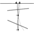
File:Checkshots-and-vertical-seismic-profiles fig3.png The source position (A or B) should be chosen so that the travel path to each receiver is as nearly v(945 × 875 (8 KB)) - 21:28, 13 January 2014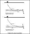
File:M91Figure162.JPG ...encountered with landing a horizontal well if the target zone is too high or too low compared to what is predicted. From Chapter 28, AAPG Memoir 91, by(600 × 682 (38 KB)) - 19:32, 30 July 2014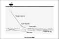
File:M91Figure161.JPG ..., with the intent of keeping the well within a specific reservoir interval or hydrocarbon zone. From Chapter 28, AAPG Memoir 91, by Mike Shepherd(800 × 534 (36 KB)) - 19:25, 30 July 2014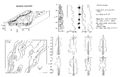
File:M31F3.jpg ...of braided channel deposits (letters on the vertical section refer to core or outcrop photographs). From Deltaic environments of deposition, 1981, Colema(2,941 × 1,884 (830 KB)) - 19:02, 15 August 2014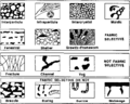
File:Porosity fig3.png ...osity groups: fabric selective, not fabric selective, and fabric selective or not. (After Choquette and Pray, 1970.)(950 × 757 (24 KB)) - 18:19, 14 January 2014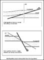
File:M91Ch13FG82.JPG ...ed sections can be seen in a vertical well drilled through a reverse fault or with a highly deviated well penetrating a normal fault. From Shepherd, M.,(600 × 820 (92 KB)) - 21:16, 29 April 2015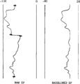
File:Log-analysis-applications fig2.png ...tive points, SP deflections are calculated and redisplayed as a baselined (or “static”) SP.(939 × 983 (9 KB)) - 16:36, 14 January 2014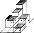
File:Using-and-improving-surface-models-built-by-computer fig18.png The cell is centered on the grid node and lies either inside or outside the polygon. The cell's area is multiplied by its z value (thicknes(835 × 790 (37 KB)) - 22:32, 13 January 2014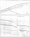
File:M31F25.jpg ...m between shot points and vertical scale is 10 milliseconds per time line, or 7.6 m (25 ft). Coleman, J. M., and D. B. Prior, 1981, Deltaic environments(1,087 × 1,348 (940 KB)) - 18:21, 18 August 2014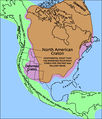
File:NacratonUSGS.jpg ...million years or so. Continents can grow when two plates collide, welding, or accreting, the two pieces together. Continents also grow when oceanic crust(512 × 599 (332 KB)) - 15:27, 19 August 2014


