Search results
Jump to navigation
Jump to search
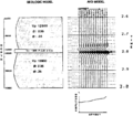
File:Amplitude-versus-offset-avo-analysis fig3.png Gas sand model.(941 × 822 (23 KB)) - 17:18, 14 January 2014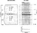
File:Amplitude-versus-offset-avo-analysis fig2.png Brine sand model.(944 × 841 (24 KB)) - 17:18, 14 January 2014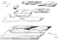
File:Geological-heterogeneities fig5.png Architectural elements of a barrier island sand body. (From Galloway and Cheng, 1985.)(1,886 × 1,310 (55 KB)) - 15:34, 14 January 2014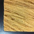
File:SandPeel.JPG A portion of a wood mounded Sand Peel.(1,280 × 1,280 (984 KB)) - 21:30, 3 July 2014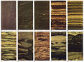
File:M31F18.jpg ...its. The dark material is transported organic debris. J. Alternating silty sand and clay layers common to the small overbank splays that cap the distributa(1,349 × 994 (1.86 MB)) - 18:16, 18 August 2014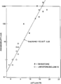
File:Full-waveform-acoustic-logging fig3.png ...core-measured permeability values for both the limestone-dolomite and the sand-shale examples. (After Burns et al., 1988.)(948 × 1,299 (12 KB)) - 14:23, 29 August 2014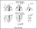
File:M91FG187.JPG Idealized log and permeability profiles for deltaic sand bodies (from Sneider et al., 1978). Reprinted with permission from, and &co(800 × 620 (61 KB)) - 20:04, 13 August 2015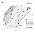
File:M91Ch11FG73.JPG Lithofacies map for the upper Piper Sand interval of the Scott field, UK North Sea (from Guscott et al., 2003). Repr(800 × 738 (128 KB)) - 15:54, 27 April 2015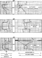
File:Quick-look-lithology-from-logs fig1.png Characteristic log shapes for different types of sand bodies set in shale, (a) Funnel shape, coarsening upward. Note that this is(945 × 1,311 (140 KB)) - 16:37, 14 January 2014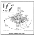
File:M91FG123.png A schematic delta showing a range of sand body types at their average dimensions, together with several oil and gas f(2,064 × 2,095 (121 KB)) - 19:40, 13 August 2015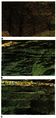
File:M31F2.jpg ...cycle of a braided channel. C. Ripple drift bedding separated by parallel sand laminations. From Deltaic environments of deposition, 1981, Coleman, J. M.,(365 × 772 (175 KB)) - 18:56, 15 August 2014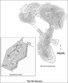
File:M91FG179.JPG Net sand isochore map of the Q reservoir in the Little Creek field in Mississippi. T(800 × 984 (103 KB)) - 21:50, 3 August 2015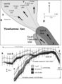
File:Mth14ch02f05.jpg ...X-Z and Y-Z showing basinward-stepping geometries exhibited by lobe-shaped sand bodies that make up the Yowlumne Sandstone. Note 660 m (2100 ft) of structu(500 × 682 (64 KB)) - 17:07, 4 December 2015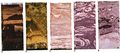
File:M31F14v2.jpg ...tary fill deposit. Diameter of cores is 13 cm (5 in.). A. Clay clasts in a sand matrix found near the base of the channel. B. Highly contorted and disrupte(1,134 × 503 (75 KB)) - 15:16, 18 August 2014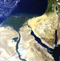
File:NileDelta.jpg ...between the lush vegetation of the Nile delta and river course and the dry sand of the Sahara can be seen spectacularly in this enhanced true colour Medium(689 × 700 (161 KB)) - 18:06, 15 August 2014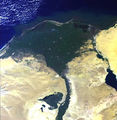
File:MainPageNileDelta.jpg ...between the lush vegetation of the Nile delta and river course and the dry sand of the Sahara can be seen spectacularly in this enhanced true colour Medium(390 × 400 (166 KB)) - 19:55, 6 April 2015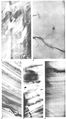
File:M31F27.jpg ...acturing in clays in the shear plane zone. C. X-ray radiograph of silt and sand core in the slump block. Note that bedding is preserved with only minor fra(760 × 1,372 (583 KB)) - 18:23, 18 August 2014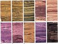
File:M31F10v2.jpg ...nds of the crevasse infilling sequence. E. Well-sorted and cross-laminated sand layers alternating with silts and silty clays associated with the lower par(1,334 × 1,000 (178 KB)) - 15:14, 18 August 2014


