Depth and thickness conversion
| Development Geology Reference Manual | |

| |
| Series | Methods in Exploration |
|---|---|
| Part | Geological methods |
| Chapter | Conversion of well log data to subsurface stratigraphic and structural information |
| Author | Jeremy M. Boak |
| Link | Web page |
| Store | AAPG Store |
Conversion of log depths to positions with respect to the surface location of a well is the first step in arriving at a consistent representation of structural or stratigraphic data for a field in a three-dimensional grid. This is particularly important in deviated wells where measured depth and thickness can differ significantly from the vertical depth and stratigraphic thickness.
Measured depth[edit]
Measured depth (MD), or drilled to depth (DD), is the depth measured (by driller or logger) to any feature of a well, whether a casing point, a sidewall core, or a significant geological marker. To use this depth in interpreting geological structure, the depth must be corrected to subsea depth or ground elevation (or rig floor or kelly bushing elevation) using information commonly found on log headers. For example, drilled depth minus kelly bushing elevation equals subsea elevation.
True vertical depth[edit]
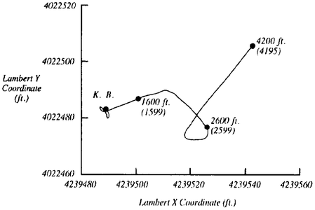
Figure 1 Surface projection of well course for a nominally vertical well. © Don Clarke, Dept. of OH Properties, City of Long Beach, CA).
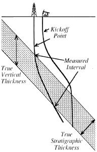
Figure 2 Well course of two types of deviated wells. True stratigraphic thickness and true vertical thickness of a dipping stratigraphic unit are shown in relation to the measured interval in a well penetrating the unit.
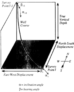
Figure 3 Segment of a curved well path showing angular and dimensional relationships between the top and bottom of the interval.
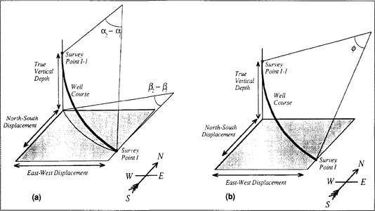
Figure 5 Circular approximations of a curved well course showing angles used for the approximations. (a) Radius of curvature method showing chords of horizontal and vertical circles. This method assumes a constant radius of curvature (constant increase or decrease in deviation between survey points). (b) Minimum curvature method showing chord of single circle and the angle ϕ, which describes the chord.


The true vertical depth (TVD) of a point within a well is the depth to that point measured on a line connecting the point to the center of the earth. It may be derived from the measured depth by correcting for the deviation of the well. Critically important to an understanding of the three-dimensional path of a well are the following facts:
- Wells are not straight; even nominally vertical holes commonly show substantial horizontal displacement even if the deviation is too small to produce a large change in true vertical depth (Figure 1).
- Wells are not commonly deviated from the surface, but rather are drilled approximately vertical to a kick-off point, where deviation is built up to a planned degree (see Wellbore trajectory). The rest of the well can be drilled at a constant angle, or the well can be returned toward the vertical to penetrate the horizon of interest (Figure 2).
- Deviation is rarely constant in a well, even when that is the objective of drilling.
As a consequence, location of the position of any point in a well must be calculated using data from well surveys and an additive formula.
For a simple case (Figure 3), in which the well course is approximated as a series of straight line segments parallel to the individual survey measurements, the formula is as follows:


where
- NSD = north-south displacement
- EWD = east-west displacement
- α = inclination angle, in degrees from the vertical, from the survey
- β = compass bearing, in degrees clockwise from north, from the survey.
- i = survey point number (i = 0 at surface)
The intervals can be defined in several ways depending on the accuracy and simplicity of calculation required. The tangential or terminal angle method (Figure 4a) assumes a constant deviation for the entire interval from one survey point to the next. Thus, the measured depths (MDi, MDi–1) for each interval coincide with the depth at the survey points, and the angle used would be for the lower survey point. Although easy to calculate, this method is likely to be substantially in error and is generally not recommended.[1][3] It is mentioned here for historical reasons, as it has been widely used. Alternatively, the angle averaging method (Figure 4b) uses the average for the two survey points at either end of the segment.
A better approximation, the balanced tangential method (Figure 4c), is derived by placing the interval depths (MDi, MDi–1) half way between the individual survey points, thus assuming that the deviation is constant in an interval around the measured point.
These formulas are derived for calculation of well positions from data at specific survey points. Calculation of the location of a stratigraphic top or other depth of interest on the well log may require interpolation of the inclination and bearing angles between survey points. The simplest approach is to interpolate linearly between the survey points above and below the point of interest:
![{\displaystyle \alpha _{m}=\alpha _{i-1}+\left[(\alpha _{i}-\alpha _{i-1})\times {\frac {({\mbox{MD}}_{m}-{\mbox{MD}}_{i-1})}{({\mbox{MD}}_{i}-{\mbox{MD}}_{i-1})}}\right]}](https://wikimedia.org/api/rest_v1/media/math/render/svg/b8329281b1ee93f9d9aa6d5984047919268ad2a8)
![{\displaystyle \beta _{m}=\beta _{i-1}+\left[(\beta _{i}-\beta _{i-1})\times {\frac {({\mbox{MD}}_{m}-{\mbox{MD}}_{i-1})}{({\mbox{MD}}_{i}-{\mbox{MD}}_{i-1})}}\right]}](https://wikimedia.org/api/rest_v1/media/math/render/svg/28e4c75d921d778b1502380f9587922d02359bbe)
where
- m = marker depth of interest
- i = next survey point below the marker depth
More sophisticated approaches to well-depth correction are the radius of curvature method (Figure 5a) and the minimum curvature method (Figure 5b). The radius of curvature method approximates the well path as a circular arc in the vertical plane, which is then wrapped around a vertical cylinder. The equations in the method (from Dailey[1]) are as follows:

![{\displaystyle {\mbox{NSD}}=(180/\pi )^{2}\sum ({\mbox{MD}}_{i}-{\mbox{MD}}_{i-1})\times (\cos \alpha _{i-1}-\cos \alpha _{i}){\times }\,(\sin \beta _{i}-\sin \beta _{i-1})/[(\alpha _{i}-\alpha _{i-1})\times (\beta _{i}-\beta _{i-1})]}](https://wikimedia.org/api/rest_v1/media/math/render/svg/1fd8601c94e7105965d58ab7fac8087d6a649350)
![{\displaystyle {\mbox{EWD}}=(180/\pi )^{2}\sum \{({\mbox{MD}}_{i}-{\mbox{MD}}_{i-1})/[(\alpha _{i}-\alpha _{i-1})\times \,(\beta _{i}-\beta _{i-1})]\}\times (\sin \alpha _{i}-\sin \alpha _{i-1})\times \,(\cos \beta _{i}-\cos \beta _{i-1})}](https://wikimedia.org/api/rest_v1/media/math/render/svg/56160275edfb56ad2fceb680dc04a667adda48f2)

where
- HD = net horizontal displacement
- b = bottom of interval of interest
- t = top of interval of interest
The minimum curvature method approximates the well path as a single circular arc. The equations in this method (from Dailey[1] and Inglis[3]) are as follows:
![{\displaystyle \phi =\cos ^{-1}[\cos \alpha _{i-1}\cos \alpha _{\rm {i}}+\sin \alpha _{\rm {i}}\sin \alpha _{i-1}\cos(\beta _{i}-\beta _{i-1})]}](https://wikimedia.org/api/rest_v1/media/math/render/svg/863317ec2fa932ebdf0899e829e1be3975804dd5)
![{\displaystyle {\mbox{TVD}}=180/\pi \sum [\tan(\phi /2)\times ({\mbox{MD}}_{i}-{\mbox{MD}}_{i-1})\times \,(\cos \alpha _{i-1}+\cos \alpha _{i})]/\phi }](https://wikimedia.org/api/rest_v1/media/math/render/svg/6b827546bddbab2313884ebf18a614f996ec476a)
![{\displaystyle {\mbox{NSD}}=180/\pi \sum [\tan(\phi /2)\times ({\mbox{MD}}_{i}-{\mbox{MD}}_{i-1})\times \,(\sin \alpha _{i-1}\cos \beta _{i-1}+\sin \alpha _{i}\cos \beta _{i})]/\phi }](https://wikimedia.org/api/rest_v1/media/math/render/svg/41a01eacca0a5afe0583aa802af1027213fae838)
![{\displaystyle {\mbox{EWD}}=180/\pi \sum [\tan(\phi /2)\times ({\mbox{MD}}_{i}-{\mbox{MD}}_{i-1})\times \,(\sin \alpha _{i-1}\sin \beta _{i-1}+\sin \alpha _{i}\sin \beta _{i})]/\phi }](https://wikimedia.org/api/rest_v1/media/math/render/svg/18736cfc87bb515eedcdd17279de7109c0384a3c)
These methods are especially useful when the deviation angle is built or decreased rapidly with respect to the survey interval.
Measured depth versus true vertical depth[edit]
Table 1 shows values for the percentage difference between measured depth and true vertical depth for varying degrees of deviation, and for the horizontal displacement (also as a percentage of measured depth) for a well segment of constant deviation. For most map and cross section scales, depth corrections for wells deviated less than 3′ are almost undetectable. For wells deviated by a larger number of degrees, large depth and horizontal displacement deviations could lead to substantial misplacements of a geological marker and the consequent distortion of structural and stratigraphic relationships.
| Deviation (α°) | Correction Factor (% of MD) | |
|---|---|---|
| TVD | HD | |
| 1 | 0.02 | 1.75 |
| 2 | 0.06 | 3.49 |
| 3 | 0.14 | 5.23 |
| 4 | 0.24 | 6.98 |
| 5 | 0.38 | 8.72 |
| 10 | 1.52 | 17.36 |
| 15 | 3.41 | 25.88 |
| 45 | 70.71 | 70.71 |
True stratigraphic thickness[edit]

True stratigraphic thickness (TST) is the thickness of a stratigraphic unit measured in the direction perpendicular to the bedding planes of the unit (Figure 2). It is a critical measure for understanding both the structural and stratigraphic development of a field. The true stratigraphic thickness is derived from the true vertical depths by the following equation:
![{\displaystyle {\mbox{TST}}=({\mbox{TVD}}_{b}-{\mbox{TVD}}_{t})\times (\cos \delta ')-[({\mbox{NSD}}_{b}-{\mbox{NSD}}_{t})^{2}+\,({\mbox{EWD}}_{b}-{\mbox{EWD}}_{t})^{2}]^{1/2}\times \sin \delta ')}](https://wikimedia.org/api/rest_v1/media/math/render/svg/ee4fe8307d22d96361ba18688c927cecc4fd2016)
In this equation, δ′ indicates the apparent dip of the bed in the direction of the horizontal displacement (Figure 6), which is written as
![{\displaystyle \delta '=\tan ^{-1}[\tan \delta \cos(\beta -\varepsilon )]}](https://wikimedia.org/api/rest_v1/media/math/render/svg/4ff30f7b036d8e9f041491abd8cd3f0a7c8d654e)
where
- δ = true dip
- β = bearing of horizontal displacement between well penetration of top and bottom of unit, or
- = tan–1HEWDb– EWDt)/(NSDb- NSDt)
- ε = bearing of dip vector
If the well is straight (no change in deviation) for the length of the interval of interest, this formula reduces to

where MD = measured depth.

It is important to note the sign convention for the two angles α and δ′. The deviation is measured from the vertical and is positive, whereas the dip is measured from the horizontal and is positive if it is in the same direction as the deviation and negative if the dip is opposite to the deviation.
An assumption made here is that the dip of the top and bottom surfaces is essentially the same. The more closely the wellbore direction approximates the dip direction, the more sensitive the thickness calculation will be to stratigraphic thickness changes (see Figure 7a). The assumption is also violated if the well traverses a zone of strong curvature in the rock such that dip changes rapidly (Figure 7b). Such changes can be corrected for if sufficient data are available, but are commonly too small to be of significance.
To calculate a TST requires survey information as well as some measure of the dip of the beds. Dip can be derived from dipmeter logs (with some caution) or from maps of geological structure. In some instances, TST maps reveal anomalies in well correlation, resulting in iterative refinement of structural and stratigraphic models. It must be recognized that, where folding occurs, stratigraphic thickness trends on maps of true stratigraphic thickness will be distorted by compression.
True vertical thickness[edit]
True vertical thickness (TVT) is the thickness of a geological unit in a well measured in the vertical direction (Figure 2). It is a valuable measure for volumetric calculations because it is unaffected by variations in the dip of the unit and can be derived by subtracting computer-gridded structural horizons. In a deviated well with a nonhorizontal unit, the TVT is difficult to calculate because, as the well steps out horizontally, it no longer cuts the bottom of the unit vertically below the point where it penetrated the top of the unit (Figure 5). If the dip is in the same direction as the deviation, the unit will appear thicker than it actually is, whereas if the dip is in the opposite direction, the unit will be shortened. The TVT is calculated according to the following formula:
![{\displaystyle {\mbox{TVT}}=({\mbox{TVD}}_{b}-{\mbox{TVD}}_{t})-[({\mbox{NSD}}_{b}-{\mbox{NSD}}_{t})^{2}+\,({\mbox{EWD}}_{b}-{\mbox{EWD}}_{t})^{2}]^{1/2}\times \tan \delta '}](https://wikimedia.org/api/rest_v1/media/math/render/svg/f4658105412a39bd16d6856b1a07d0e96b5f6d4c)
See also[edit]
- Introduction to geological methods
- Subsurface maps
- Effective pay determination
- Multivariate data analysis
- Cross section
- Fluid contacts
- Geological heterogeneities
References[edit]
- ↑ 1.0 1.1 1.2 1.3 1.4 1.5 Craig, J. T., Jr., and B. V. Randall, 1976, Directional survey calculation: Petroleum Engineer, March, p. 38–54.
- ↑ Dailey, P., 1977, A guide to accurate wellbore survey calculations: Drilling-DCW, May, p. 52–59 and 118–119.
- ↑ 3.0 3.1 Inglis, T. A., 1987, Directional Drilling, Petroleum Engineering and Development Studies, Volume 2: London, Graham and Trorman, chap. 9, p. 155–171.
External links[edit]
| find literature about Depth and thickness conversion |