Forward modeling of seismic data
| Development Geology Reference Manual | |

| |
| Series | Methods in Exploration |
|---|---|
| Part | Geophysical methods |
| Chapter | Forward modeling of seismic data |
| Author | George Mellman, Paul A. Kunzinger |
| Link | Web page |
| Store | AAPG Store |
Forward numerical modeling of seismic data is the use of geological models of the earth to simulate seismic field experiments. Models can be one, two, or three dimensional and consist of depth horizons and associated P wave velocities, S wave velocities, and densities
The most common use of forward modeling is for verification of structural and stratigraphic interpretations. For example, synthetic seismic sections derived from forward modeling can be compared to stacked sections to verify the original interpretation. If needed, the original interpretation or model is altered and the process repeated until a desired correlation between the actual data and modeled results is observed (see Synthetic seismograms).
An example of the use of modeling to aid in stratigraphic interpretation is the use of amplitudes of seismic data to infer the thickness of a thin sand layer. If layer thickness is less than a wavelength, variations and thickness appear as tuning effects, with systematic changes in amplitude and wave shape correlating directly with sand thickness. Producing forward models with varying sand thickness using well data to calibrate, and comparing these synthetics with observed seismic sections, provides a means of accurately determining sand thickness where well data are sparse or absent.
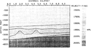
Another use of forward modeling is the determination of the seismic expression of expected features of the geology. Figures 1 and 2 illustrate the use of seismic modeling to determine if porosity in a carbonate reef interval is detectable on seismic data. Figure 1 is a strike cross section through a 3-D geological model representing a carbonate reef play. Reef structures are located in the interval between the depths of 2500 and depth::3500 ft. The structure located on the left side of the cross section contains porosity, while the structure on the right is tight. Porosity is represented in the model by a lower interval velocity and lower density than the surrounding rock (see Porosity).
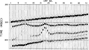
This study included the generation of two synthetic seismic sections using 3-D ray tracing techniques. One section represents a synthetic stacked seismic section (created using normal incidence ray tracing), while the second represents a synthetic migrated section (created using image ray tracing). The objective of modeling is to determine if there is a noticeable difference between the seismic signature of the tight carbonate and that of the porous carbonate. The synthetic migrated section is illustrated in Figure 2. The positive event at traces 20 through 26 and between 325 and 375 msec represents the top of the tight anticlinal structure. There is a distinct character change of this seismic event corresponding to a change in porosity in the geological model. The porosity is identified by the dim spot on traces 6 through 11 and the velocity pulldown of the underlying event. The results from this modeling indicate that seismic data could be used to identify porosity in this geological setting. A good description of modeling methods and a number of case study examples can be found in Fagin.[1]
Methods of forward modeling


A number of forward modeling methods are available, and the choice of method generally depends on a tradeoff between the accuracy necessary and the desired computing time. In general, the type of data to be modeled, the complexity of the model, and the aspects of the data that need to be accurately modeled dictate the method that should be used.
While field experiments always produce shot gathers, there are approximations available in numerical modeling that produce other data types directly. To simulate stacked data, for example, an exploding reflector model is often used. Virtual explosive sources are placed along all reflecting interfaces, with source strength proportional to the normal incidence reflection coefficient at that interface. This method produces accurate traveltimes and good zero offset amplitudes for geometric arrivals. Diffraction amplitudes are not accurate in this approximation, and multiples are not present. However, a complete stacked section can be generated in about the time it takes to generate a single shot gather. This efficiency makes the exploding reflector model the method of choice for most stacked section simulations. Another approximation, called image rays, [2] makes it possible to simulate time-migrated data directly, again with approximations, but with significant time savings.
There are two classes of seismic modeling: ray tracing and wave equation methods. Implementation of both classes exists for one, two, and three dimensions; shot gather; common midpoint (CMP) gather; and stacked data simulation.
Ray theory uses the fact that energy in the form of rays travels along minimum time paths in the model. As in optics, rays bend when velocities change, obeying Snell's law, and are partially reflected when velocity or density discontinuities are encountered. Traveltimes of reflected arrivals correspond to the times of the minimum time paths, while amplitudes are a combination of geometric spreading and reflection coefficient. The reflection coefficient, based on the Zoeppritz equations for elastic media, depends on the velocities and densities on both sides of the interface, as well as on the incidence angle of the ray.
Ray methods usually give very accurate traveltimes and accurate amplitudes for geometric arrivals if the model is sufficiently smooth. These methods are efficient, and computing time is low to moderate. Diffractions and multiple reflections can be added, though at high computing times and never with complete accuracy. Ray methods are the methods of choice for many structural verification problems and are quite useful for stratigraphic problems if the interfaces are reasonably smoothly varying.
Wave equation methods solve the propagation problem over the entire model, rather than performing local solutions as in ray methods. Two commonly used wave methods are the Kirkhhoff[3] method and the finite difference method.[4] Kirkhhoff methods use a local approximation to obtain a reflected wave field at an interface. These methods can provide accurate traveltimes for geometric and diffracted arrivals and accurate amplitudes for geometric arrivals, even in complex media. Diffraction amplitudes are usually not very accurate for these methods, and multiples are usually absent. Computing time is moderate.
Finite difference methods can provide very accurate results even in the most complex media. These methods provide exact numerical solutions and can include all wave phenomena, such as diffractions, multiples, and ground roll. The only limitations on finite difference methods are imposed by computing time, which is high in two dimensions and very high in three dimensions. This effectively limits grid size and hence the resolution obtainable. However, these are still the methods of choice for highly faulted complex models for which amplitude accuracy is important.
Often, the largest limiting factor on the accuracy of a forward model is not the method chosen to solve the problem, but rather the inappropriate use of one- or two-dimensional models of the geology when two- or three-dimensional models are necessary. The controlling factor for the model dimension is not the dimension of the data but rather the complexity of the geology. The presence of appreciable dip requires the use of two- or three-dimensional models. The presence of out-of-plane structures or dip requires the use of three-dimensional modeling. Failure to use models of the correct dimension can give rise to appreciable traveltime and amplitude error, as well as missing or misinterpreted arrivals.
See also
- Seismic data acquisition on land
- Seismic interpretation
- Cross-borehole tomography in development geology
- Synthetic seismograms
- Vertical and lateral seismic resolution and attenuation
- Borehole gravity
- Displaying seismic data
- Three-dimensional seismic method
- Magnetics
- Full waveform acoustic logging
- Electrical methods
- Seismic migration
- Basic seismic processing
- Marine seismic data acquisition
- Introduction to geophysical methods
- Seismic data - mapping with two-dimensional data
- Seismic inversion
- Checkshots and vertical seismic profiles
- Amplitude versus offset (AVO) analysis
- The gravity method
References
- ↑ Fagin, S. W., 1991, Seismic Modeling of Geologic Structure: Tulsa, OK, Society of Exploration Geophysicists, Geophysical Development Series, v. 2.
- ↑ Hubral, P., 1977, Migration: Some ray theoretical aspects: Geophysical Prospecting, v. 25, p. 739-745.
- ↑ Hilterman, F. J., 1970, Three-dimensional seismic modeling: Geophysics, v. 35, p. 1020–1037., 10., 1190/1., 1440140
- ↑ Kelley, K. R., R. W. Ward, S. Treitel, and R. M. Alford, 1976, Synthetic seismograms—a finite difference approach: Geophysics, v. 41, p. 2–27., 10., 1190/1., 1440605