Reservoir fluids
| Oil Field Production Geology | |

| |
| Series | Memoirs |
|---|---|
| Part | The Production Geologist and the Reservoir |
| Chapter | Reservoir Fluids |
| Author | Mike Shepherd |
| Link | Web page |
| PDF file (requires access) | |
| Store | AAPG Store |
This article describes the physics of how oil, gas, and water interact with each other and the rock. The basic concepts of wettability, capillary pressure, and relative permeability are important. This is knowledge required to understand how reservoirs behave. Physical processes also control the distribution of oil and water in a reservoir, and an understanding of these will help the production geologist to estimate the in-place hydrocarbon volumes.
Wettability[edit]
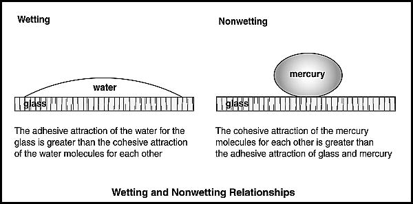
Figure 1 Wetting and nonwetting relationships between fluids and rocks have a major effect on the static and dynamic behavior of hydrocarbons in reservoirs.
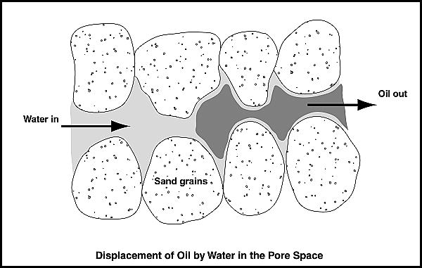
Figure 2 In a water-wet reservoir, water wets the surface of the grains, and hydrocarbons occupy the central parts of the pore space. Moving water will displace the oil from the center of the pores (from Clark et al).[1] Reprinted with permission from SPE.


Much of the physical processes that control the fluid distribution in a reservoir occurs at the molecular level. Individual molecules show an attraction for each other resulting from weak intermolecular forces. In a body of liquid, the tendency is for the molecules to be pulled in toward the center of the body; surface tension forces will reduce the surface area of the liquid to a minimum. For an interface between two immiscible liquids, the term interfacial tension is used for the force acting to reduce the area of contact between two different fluids.
Where two immiscible liquids, or a liquid and a solid, are in contact with each other, the surface molecules of each substance are also attracted to each other across the interface by weak intermolecular forces.
Therefore, at a solid-liquid boundary interface, the molecules of the liquid are subjected to opposing forces of attraction; in the first instance, the liquid is attracted by its own molecules and secondly by the molecules of the solid across the boundary. The degree to which force is dominant controls what is termed the wettability.[2] For instance, glass is water wet, in that water will spread across the surface of a glass plate as a thin sheet. The adhesive attraction of the water for the glass is greater than the cohesive attraction of the water molecules for each other. A liquid such as mercury will form globules on a glass surface and is nonwetting. The cohesive attraction of the mercury molecules for each other is greater than the adhesive attraction of glass and mercury (Figure 1).
Where a reservoir rock is water wet, the water forms a thin film over most of the grain surfaces and will also fill the smaller pores. The oil or gas will occupy the remaining, more central volume of the pore system. Conversely, in a reservoir that is oil wet, it is the oil that covers the grain surface and occupies the smaller pores; the water is located centrally within the pore structure.[3]
Most reservoirs were water wet before oil migration started; the major mineral phases in reservoirs such as quartz, carbonate and dolomite are all water wetting prior to coming in contact with oil.[4] Following oil migration, sandstone reservoirs can end up as predominantly water wet, predominantly oil wet, or more frequently in a mixed-wettability state, that is, somewhere in between oil wet and water wet. Carbonate reservoirs are commonly described as showing mixed wettability tending to oil wet.[5][6] The degree of wettability can vary even within a single reservoir. The rocks in the reservoir will show a variety of mineral types, each mineral with its own wetting characteristics. Other variables affecting wettability include the wetting nature of the numerous compounds comprising crude oil and the degree to which polar compounds from the oil are absorbed onto the rock surface.[3]
Waterfloods produce more efficient sweeps in water-wet reservoirs than in oil-wet systems. Water forced to move through a water-wet pore system will displace the oil from the center of the pores relatively efficiently (Figure 2). Water will also be drawn into the smaller pores, displacing oil into the main flow pathways. In an oil-wet sandstone, the oil forms a film around the sand grains and water will move through the center of the pores, particularly the larger connected pores. The pathway for the water here is less tortuous than in water-wet sandstones, and the water will move through the rock more quickly, bypassing a large volume of oil. Rapid water breakthrough to the production wells typically occurs, and oil rates will drop significantly once this happens. Nevertheless, the film of oil around the grains can survive as a continuous path to a production well after water has broken through. Because of this, a continuous flow of oil can still be maintained in oil-wet reservoirs by injecting large volumes of water.[7]
Buoyancy forces in reservoir fluids[edit]
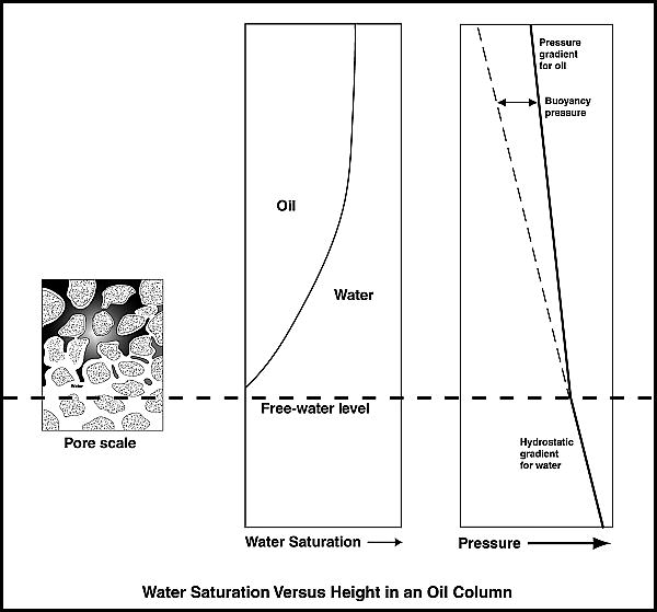
Figure 3 Water saturation decreases with height in an oil column. The volume of water is a function of the balance of capillary forces pulling the water up from the oil-water interface and the force of gravity acting together with the density contrast between the reservoir fluids, tending to pull the water down.
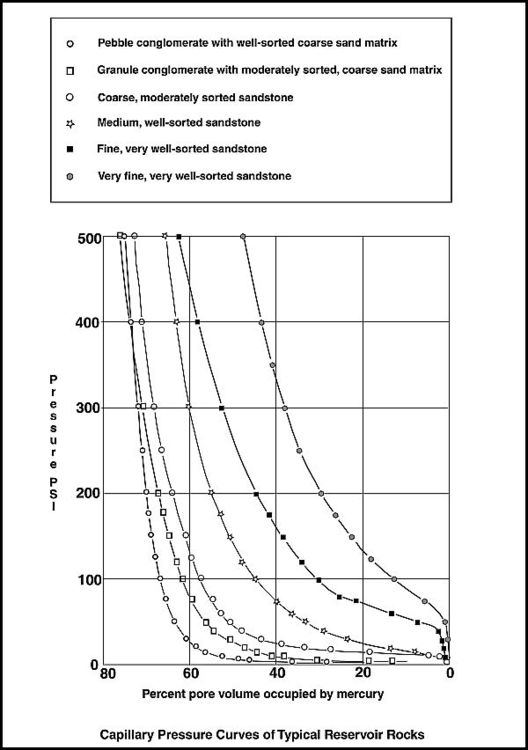
Figure 4 The shape of the curves on a capillary pressure plot reflects the grain sorting and the connection of pores and pore throats within the various rock types. The longer the plateau shown by the capillary curve, the better is the reservoir quality of the rock (from Sneider et al).[8] Reprinted with permission from SPE.


When hydrocarbons migrate into a trap, the buoyancy force exerted by the lighter oil (or gas) will push the water that was previously in the pore space sideways and downward. However, not all of the water is displaced; some of it will be held by capillary forces within the pores. Narrower capillaries, pores with smaller pore throats, hold onto water the strongest.
The two forces acting on the fluids in the pore space are controlled by physical laws. The equation for the buoyancy pressure is given by

where Pb is the buoyancy pressure; ρw and ρnw are the specific gravities of the wetting and nonwetting phases respectively; g is the acceleration of gravity; and h is the height above the free-water level.
The equation for capillary forces is given by

where Pc is the capillary pressure, sigma is the interfacial tension, thetas is the contact angle between the wetting fluid and the solid surface, and r is the capillary (pore throat) radius.[2]
The volume of water remaining at a given height in a reservoir is a function of the balance of capillary forces pulling the water up from the hydrocarbon-water interface and the force of gravity acting together with the density contrast between the reservoir fluids, acting to pull the water down.[9] Thus, a given part of the pore space within the hydrocarbon leg can contain both hydrocarbons and water. The fraction (percentage) of water to total fluid volume is termed the water saturation.
For an oil field, the capillary-bound water comprises a continuous column of water within the oil leg, which will have a hydrostatic pressure gradient controlled by the water density. The oil is located in the remaining pore space as a continuous phase and will have a pressure gradient controlled by the (lower) oil density (Figure 3). Although oil and water can coexist in the same localized volume of rock, the pressures acting on the two fluids are different. The difference in pressure between the oil and water phases increases with height above the free-water level. The free-water level is the level at which the water-hydrocarbon interface would theoretically stand in a large open hole drilled through the oil column.[10] In this situation, only gravity and buoyancy forces control the fluid distribution in the borehole.
As the buoyancy pressure increases with height above the free-water level, the oil phase will displace more water from increasingly smaller pore volumes. The effect of this is that hydrocarbon saturations increase with height above the hydrocarbon-water contact. The relationship between capillary and buoyancy forces thus controls the static distribution of fluids in oil and gas pools. Knowledge of these relationships is fundamental to the accurate calculation of hydrocarbon volumes within a reservoir.
Capillary pressure is typically measured in the laboratory by injecting mercury under pressure into a core plug. The mercury is a nonwetting phase, which replicates the behavior of hydrocarbons in reservoir rocks. The procedure simulates the entry of hydrocarbons into a water-wet rock and the way in which buoyancy pressure increases with height in the hydrocarbon column.
Mercury will not enter the rock immediately. The pressure required to do this will depend on the radius of the pore throats, the contact angle, and the mercury-air interfacial tension. The pressure at which the mercury effectively enters the pore network is termed the displacement or entry pressure.[2] Lower entry pressures are found in the better quality reservoir rocks, that is, those with larger pore throat diameters. A cap rock with tiny capillaries, shale for instance, has a very high displacement pressure. The displacement pressure for a cap rock can be so high that the tightly bound water in the pore space of the shale will prevent the oil from entering and the oil remains trapped in the underlying reservoir rock.[10][11]
With increasing injection pressure, more and more mercury is forced into the rock. The shape of the curves on a capillary pressure plot reflects the grain sorting and the connection of pores and pore throats. The longer the plateau shown by the capillary curve, the better the reservoir quality. Poorly sorted, fine-grained sediment with narrow pore throats will retain water to higher pressures than coarser grained, better sorted sediments. A homogenous reservoir rock can be represented by a single capillary pressure curve. By contrast, a heterogenous reservoir will have a family of rock types, each with its own capillary pressure curve (Figure 4).
Petrophysicists will use capillary pressure curves as the basis for deriving a water saturation versus height relationship for a reservoir.[2]
Relative permeability[edit]
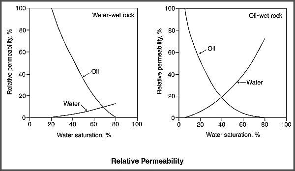
Figure 5 When more than one fluid phase is present, the permeability of one phase is reduced by the presence of the other phases within the pore system. Relative permeability curves display these relationships. The plots show a water- displacing-oil relative permeability curve for a water-wet rock and a water-displacing-oil relative permeability curve for an oil-wet rock (modified from Hawkins).[12] Reprinted with permission from the AAPG.
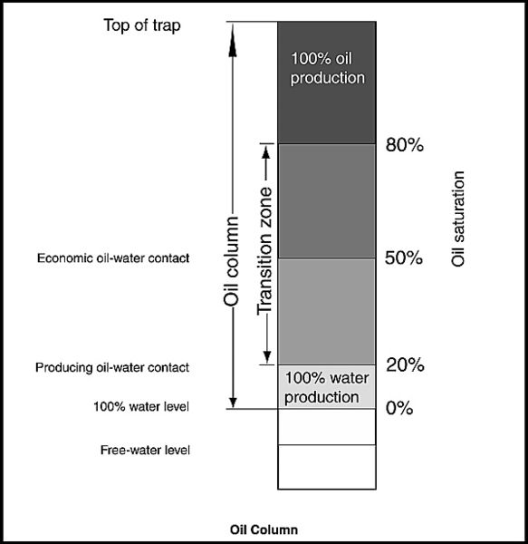
Figure 6 The decrease in water saturation with height controls the producing behavior of an oil column. Redrawn from Jennings,[13] with permission from the AAPG.


Permeability is the measure of the ease of movement of fluid through the pore space in a rock. Where more than one fluid phase is present (e.g., oil and water), the permeability of one phase is reduced by the presence of the other phase within the pore system. In this instance, the permeability to a particular fluid is called the relative permeability.[12]
For water-wet reservoirs, Craig[14] gave some general water-oil relative permeability end points. Water will start flowing along with oil once the water saturation is greater than roughly 20–25%. This value is the irreducible water saturation; the volume of water bound and immobilized by adhesive attraction to the surface of the pores. Oil will stop flowing where the water saturation in the rock is about 70–80%. When this happens, there will not be enough oil to provide a continuous volume throughout the rock. Interfacial tension will cause the oil stream to snap off and fragment into immobilized globules and strands of residual oil.
The relative permeability end points may vary significantly between reservoirs; the quoted values can be considered as approximate. The relative permeability of water and oil as a function of water saturation is illustrated by relative permeability curves (Figure 5).
The static distribution of fluids in unproduced reservoirs[edit]
The producing behavior in an oil column will vary according to the fluid saturations.[13] Several zones can be defined (Figure 6):
- The zone of 100% oil production. This is located above the height where the water saturation is less than the relative permeability end point to water, e.g., less than 20% water saturation. The water is immobile and only oil will flow.
- The oil-water transition zone. Both water and oil are produced in this interval. The water saturations here lie between the end points at which the relative permeability to water is zero and the relative permeability to oil is zero. In coarse-grained sediments, the transition zone may be less than a meter thick; in very fine-grained sediments, it may be many tens of meters thick or more. In some reservoirs, the entire oil column may be within the transition zone.[15]
- The zone of 100% water production. This is that part of the oil column where there is still a small volume of oil present. However, its relative permeability is zero, so the oil will not flow, whereas the water will.
- The 100% water level. This is the level at which the buoyancy pressure of the oil equals the capillary displacement pressure of the reservoir rock. The 100% water level is the level above which the reservoir rock has a water saturation less than 100%.[10] It is effectively the base of the oil column, although some authorities state that a small volume of residual oil may be present below this level (e.g., Jennings[13]).
- The free-water level. At some point below the base of the oil column in a water-wet reservoir is the free-water level. The free-water level is a horizontal surface where theoretically the water would stand in a large open hole unconstrained by the effects of capillary forces. At this point, the buoyancy pressure is zero.
The definition of an oil-water contact varies somewhat within the literature.[13] The commonly used definitions are:
- The base of the oil column corresponding to the 100% water level. This is the most frequently used definition for estimating the oil in place volume.
- The producing oil-water contact, which is located at the base of the transition zone. This is the lowest point at which oil can be produced.
- The economic oil-water contact, the point where enough oil is produced in the total fluid to make the well economically viable. This is nominally the point corresponding to the 50% oil saturation level.
- The top of the transition zone. Only oil is produced above this point.
Tilted oil-water contacts[edit]

Some fields have a hydrodynamically tilted oil-water contact (Figure 7). This results from variations in aquifer pressure associated with the movement of water in the subsurface, mainly as a result of a mobile artesian aquifer or basin dewatering.[16] The tilts are toward the direction of reducing pressure and are generally less than 2deg in gradient.[17][18]
Perched oil-water contacts[edit]
Sometimes a new well will find an oil-water contact significantly shallower than the common oil-water contact established in the wells drilled so far in the field, yet there is evidence for pressure communication between the new and old wells (Figure 7). The shallower oil-water contact may be a perched oil-water contact. These are common features yet are hardly ever mentioned in the literature. Perched oil-water contacts result from the trapping of small to moderate volumes of water when the oil initially migrated into the reservoir. Normally, the water will be displaced down and sideways as the oil enters. However, if a barrier prevents the water from being moved out of the way, the water will remain where it is.
Sometimes a localized perched oil-water contact can be found more than 50 m (164 ft) higher than the established oil-water contact. For example, in the Fulmar field, UK North Sea, a perched oil-water contact in the north of the field was found at 3228 m (10,590 ft) true vertical depth subsea (TVDSS), 73 m (240 ft) higher than the main oil-water contact at 3301 m (10830 ft) TVDSS. Pressure and production data indicate communication within the oil column between the two areas.[19]
The most common type of perched oil-water contact is a downwarped thin reservoir with the downward flow of water blocked by a sand pinch-out or a sealing fault. Local synclinal areas flanked by sealing faults can also retain water.[20]
References[edit]
- ↑ Clark, N. J., H. M. Shearin, W. P. Scultz, K. Garms, and J. L. Moore, 1958, Miscible drive—Its theory and application: Journal of Petroleum Technology, v. 10, SPE Paper 1036-G, p. 11–20.
- ↑ 2.0 2.1 2.2 2.3 Vavra, C. L., J. G. Kaldi, and R. M. Sneider, 1992, Geological applications of capillary pressure: A review: AAPG Bulletin, v. 76, no. 6, p. 840–850.
- ↑ 3.0 3.1 Anderson, W. G., 1986, Wettability literature survey: 1. Rock/oil/brine interactions and the effects of core handling on wettability: Journal of Petroleum Technology, SPE 13932, v. 38, no. 10, p. 1125–1144.
- ↑ Abdallah, W., et al., 2007, Fundamentals of wettability: Oilfield Review, Summer 2007, v. 19, no. 2, p. 44–61.
- ↑ Treiber, L. E., D. L. Archer, and W. W. Owens, 1972, A laboratory evaluation of the wettability of fifty oil-producing reservoirs: Presented at the Society of Petroleum Engineers 46th Annual Fall Meeting, October 3–6, New Orleans, SPE Journal, SPE Paper 3526, v. 12, no. 6, p. 531–540.
- ↑ Chilingar, G. V., and T. F. Yen, 1983, Some notes on wettability and relative permeabilities of carbonate reservoir rocks: II: Energy Sources, v. 7(1), no. 7, p. 67–75.
- ↑ Anderson, W. G., 1987, Wettability literature survey: 6. The effects of wettability on waterflooding: Journal of Petroleum Technology, SPE 16471, v. 39, no. 12, p. 1605–1622.
- ↑ Sneider, R. M., F. H. Richardson, D. D. Paynter, R. E. Eddy, and I. A. Wyant, 1977, Predicting reservoir rock geometry and continuity in Pennsylvanian reservoirs, Elk City, Oklahoma: Journal of Petroleum Technology, v. 29, no. 7, SPE Paper 6138, p. 851–866.
- ↑ Arps, J. J., 1964, Engineering concepts useful in oil finding: AAPG Bulletin, v. 48, no. 2, p. 157–165.
- ↑ 10.0 10.1 10.2 Schowalter, T. T., 1979, Mechanics of secondary hydrocarbon migration and entrapment: AAPG Bulletin, v. 63, no. 5, p. 723–760.
- ↑ Berg, R. R., 1975, Capillary pressures in stratigraphic traps: AAPG Bulletin, v. 59, no. 6, p. 939–956.
- ↑ 12.0 12.1 Hawkins, J. T., 1992, Relative permeability, in D. Morton-Thompson and A. M. Woods, eds., Development geology reference manual: AAPG Methods in Exploration Series 10, p. 226–228.
- ↑ 13.0 13.1 13.2 13.3 Jennings, J. B., 1987, Capillary pressure techniques: Application to exploration and development geology: AAPG Bulletin, v. 71, no. 10, p. 1196–1209.
- ↑ Craig, F. F., 1971, The reservoir engineering aspects of waterflooding, monograph series: Richardson, Texas, Society of Petroleum Engineers, 144 p.
- ↑ Fanchi, J. R., R. L. Christiansen, and M. J. Heymans, 2002, Estimating oil reserves with oil/water transition zones: SPE Reservoir Evaluation and Engineering, v. 5, no. 4, SPE Paper 79210, p. 311–316.
- ↑ Hubbert, M. K., 1953, Entrapment of petroleum under hydrodynamic conditions: AAPG Bulletin, v. 37, p. 1954–2026.
- ↑ Dennis, H., J. Baillie, T. Holt, and D. Wessel-Berg, 2000, Hydrodynamic activity and tilted oil-water contacts in the North Sea, in K. Ofstad, E. J. Kittilsen, and P. Alexander-Marrack, eds., Improving the exploration process by learning from the past: Norwegian Petroleum Society Special Publication 9, p. 171–185.
- ↑ Dennis, H., P. Bergmo, and T. Holt, 2005, Tilted oil-water contacts: Modelling the effects of aquifer heterogeneity, in A. G. Dore and B. A. Vining, eds., Petroleum geology: Northwest Europe and global perspectives: Proceedings of the 6th Petroleum Geology Conference, Geological Society (London), v. 1, p. 145–158.
- ↑ Stockbridge, C. P., and D. I. Gray, 1991, The Fulmar field, Blocks 30/16 and 30/11b, UK North Sea, in I. L. Abbots, ed., United Kingdom oil and gas fields, 25 years commemorative volume: Geological Society (London) Memoir 14, p. 309–316.
- ↑ Weber, K. J., 1995, Perched hydrocarbon-water contacts—A common but poorly understood phenomenon: Abstracts of the 57th EAGE Conference, Glasgow, F035.