Seismic data acquisition on land
| Development Geology Reference Manual | |

| |
| Series | Methods in Exploration |
|---|---|
| Part | Geophysical methods |
| Chapter | Seismic data acquisition on land |
| Author | Dale M. Short |
| Link | Web page |
| Store | AAPG Store |
There are four basic components of land seismic acquisition:
- Location—knowing where the line is to be shot
- Source—some means of transmitting acoustic energy into the subsurface
- Receivers—a means of gathering the energy as it is reflected by changes in rock properties in the subsurface
- Recorder—a device for preserving the gathered information for processing
Location
Once the location of the seismic program (a line or group of lines) is laid out on a program map, and prior to any field activities, permits must be obtained from governments and/or private landowners. Permits are commonly granted, and in the case of private ownership, fees are paid for trespass and/or damages. During the permitting phase of the program, many potential problems with the location of the program must be diagnosed, such as impassable terrain, areas restricted to vehicular traffic (e.g., national parks and wildlife sanctuaries) or other obstructions (e.g., towns, buildings, and refineries). The actual surveying of the program is fairly straightforward. Standard survey techniques for determining x, y, and z coordinates generally provide adequate accuracy, given sufficient control. However, in remote or previously unsurveyed areas, satellite stations may be necessary to provide accurate points of reference. Above all, reproducibility of the survey is necessary to be able to go back and drill at the shotpoint interpreted as “the place to drill.”
Source
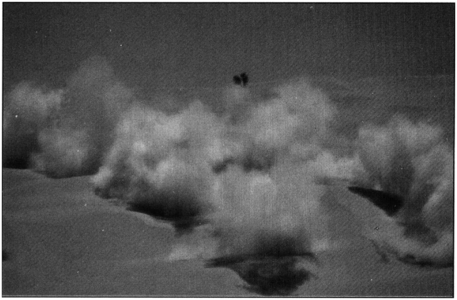
Figure 1 Dynamite shot pattern being detonated in the desert. (Photo. Copyright: Western Atlas International.)
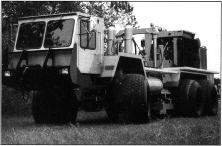
Figure 2 Vibrator truck. (Photo. Copyright: Western Atlas International.)
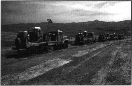
Figure 3 Vibrator truck in a simple “in line” array. (Photo. Copyright: Western Atlas International.)
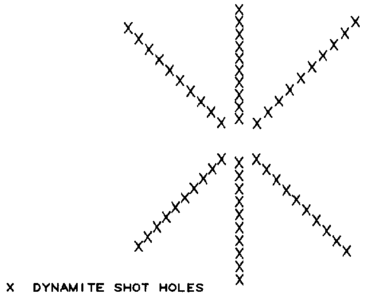
Figure 4 Six-point star shot pattern.
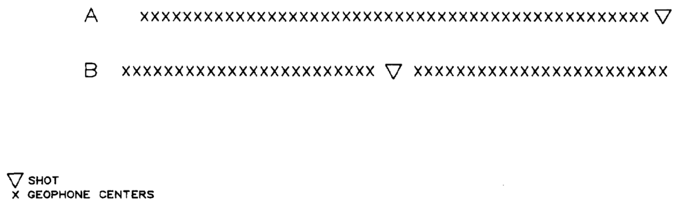
Figure 5 (a) Off end shooting. (b) Split spread shooting.


Numerous energy sources exist, including various explosives (dynamite and primacord) (Figure 1), gas or air guns, weight drop mechanisms, vibrator systems (Figure 2), and even firearms, such as .50 caliber machine guns (fired single shot) and shotguns. Applications, advantages, and disadvantages of some of these sources are listed in Table 1.
| Source | Application | Advantages | Disadvantages |
|---|---|---|---|
| Explosives | General acquisition | Short, broad band pulse. Source can be placed below weathering layer. | Requires expensive shothole drilling. Frequency dependent on material in which explosion occurs. Dangerous to handle. |
| Vibrators | General acquisition | Minimal cultural and environmental impact. Controlled frequency source. Narrow frequency band can increase signal to noise ratio. No shot holes required. | Shallow weathering can cause statics problems. Base-plate to ground coupling can be a problem. More complex recording and processing. |
| Gas or air guns | Acquisition in rough terrain | Cheap. Heli-portable. Can use multiple sources. No shot holes required. | Limited energy penetration. Ground roll problems. Requires longer offsets. Shallow weathering can cause statics problems. |
| Weight drop | General acquisition. Desert acquisition. | Cheap. No shot holes required. | Cannot synchronize sources. Ground roll problems. Requires longer offsets. Shallow weathering can cause statics problems. |
Explosive sources are typically buried. Some examples include dynamite in “shot holes” ranging in depth from 10 to length::300 ft (3 to 100 m) and primacord in trenches covered by a few inches of soil. However, in some cases, both of these sources can be exposed on the surface. The other sources are generally truck mounted, but specialty vehicles are often used as transport when required by surface or environmental conditions (e.g., wet ground or arctic tundra). Many areas are inaccessible, and require helicopter support. In such cases, all aspects of the operation must be portable enough to be loaded onto helicopters and then move by hand into position.
Source locations, or shotpoints, are sometimes single points, but are often positioned in arrays. A shotpoint array is specifically designed to impart maximum seismic energy into the ground and/or minimize seismic noise such as ground roll. Arrays may be as simple as lining up several vibrator trucks (Figure 3) or as complex as drilling and shooting six-point star patterns (Figure 4). Shotpoint intervals range from over depth::1000 ft (300 m) to less than length::100 ft (30 m) and are often in intervals evenly divisible into 5280. However, modern seismic is typically shot with fairly short shotpoint intervals ranging from 55 to length::440 ft (17 to 134 m). Shooting patterns can be off end or split spread (Figure 5). Split spread is probably the most common and has an equal number of geophone groups in front of and behind the shot.
Receiver

A geophone is a mechanical device that transforms seismic energy into electrical voltage (Figure 6). Individual geophones are often wired together and configured in arrays along a cable. These arrays are designed much the same as source arrays and for the same basic reasons, that is, to maximize detection of reflected energy and to reduce the amount of noise. However, it is important that for any geophone array to work, the individual phones must be properly planted and not just thrown out on the ground, stuck into trees, hung in bushes, or set on rocks.
There are two basic types of cable systems: analog and telemetry. The analog systems have a pair of wires for each geophone group and several additional pairs of wires for roll-along. (Roll-along allows for shooting to continue while geophones are picked up behind the shot and moved into position in front of the shot.) For example, a 96-channel system may have 72 pairs of wires for the front part of the cable and the same for the back. Likewise a 240-channel system may have as many as 144 pairs of wires. The advantage to this sort of hard-wired system is that it can be used in most any type of terrain. However, if these cables get too long, the signal may be attenuated by leakage or obliterated by 60-Hz noise. These problems can be overcome by telemetry systems (also known as distributed systems), which have an analog connection from the geophone group to a processor. The processor or station box amplifies the analog signal, filters, digitizes, and transmits the digital signal to the recording facility by wire, optical fiber, or radio. Hybrids of these two systems can be used to accommodate varying field conditions.
Recording
Modern recording systems can be as varied as the source and the detection systems. The recording system does many of the same things to the data that the processor or station box in the distributed systems does, such as amplifying, filtering, multiplexing, and digitizing, but in the end, the data are recorded (generally on magnetic tape). Parameters such as sample rate, record length, and recording filters can be controlled in the recording process. These instruments are often the limitation in the number of channels that can be recorded. Typical modern units record up to 120 channels, but these can be linked together to form master-slave units. Higher numbers of channels are the wave of the future in recording systems.
Final remarks
Modern land seismic acquisition has advanced from a shallow structural determination technique to a sophisticated subsurface measuring tool. Future developments, such as cables with increased numbers of channels, telemetry, and more advanced electronics have spawned areas of specialization beyond any one person's grasp. This necessitates good communication between the explorers and their partners in the acquisition and processing sides of the business. Knowing what specific information the explorer is looking for allows the acquisition and processing personnel to properly design a program that maximizes resources, prevents overkill, and accomplishes the task at hand.
See also
- Three-dimensional seismic method
- Marine seismic data acquisition
- Introduction to geophysical methods
- Checkshots and vertical seismic profiles
External links
| find literature about Seismic data acquisition on land |