Artificial lift
| Development Geology Reference Manual | |

| |
| Series | Methods in Exploration |
|---|---|
| Part | Production engineering methods |
| Chapter | Artificial lift |
| Author | D. D. Smallwood |
| Link | Web page |
| Store | AAPG Store |
Artificial lift refers to the mechanical lifting of wellbore fluids to the surface. Mechanical lifting of wellbore fluids is required when reservoir pressure is insufficient to drive reservoir fluids to the surface. Artificial lift equipment also can be used to increase production from flowing wells by reducing the producing bottomhole pressure.
A number of different types of artificial lift systems are currently in use. The four primary artificial lift systems are
- Electric submersible pump (ESP)
- Gas lift
- Hydraulic pump (piston and jet pump)
- Beam pump
Electric submersible pumps[edit]
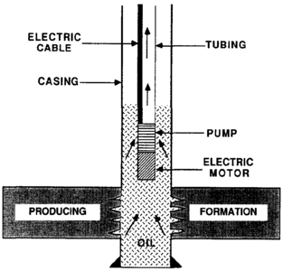
Figure 1. Electric submersible pump.[1]
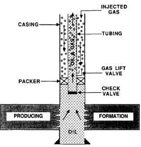
Figure 2 Gas lift system.[1]
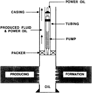
Figure 3 Hydraulic piston pump.[1]

Figure 4 Beam pumping system.[1]


An electric submersible pump (ESP) consists of a centrifugal pump coupled to an electric motor. The pump and motor combination is run in the well on the bottom of the tubing string and is set below the operating fluid level in the well (Figure 1).
The electric motor powers a centrifugal pump that forces fluid into the pump up through the tubing and out at the surface. The electric motor is powered by an electric cable strapped to the side of the tubing string. Lift capacity for each pump is adjusted by changing the number of stages in the centrifugal pump and/or by changing the horsepower of the electric motor.
Electric submersible pumps are beneficial in wells that must lift high volumes of fluids from less than depth::10,000 ft deep. ESPs are often used in the late stages of waterflooding where high water cuts require lifting large production volumes from each well.
Gas lift[edit]
Gas lift is the process of lifting fluids from the wellbore using high pressure gas as the energy source. Downhole gas lift equipment consists of a series of gas lift valves spaced at predetermined depths in the tubing string. The tubing string is set in a packer above the casing perforations (Figure 2). Gas is normally injected down the tubing/casing annulus and enters the tubing via the gas lift valves. A surface gas compressor is used to provide the high gas pressure required to open the gas lift valves.
Gas lift systems move the reservoir fluids to the surface by reducing the hydrostatic pressure of the fluid column in the tubing below reservoir pressure. The injected gas expands as it moves upward in the tubing, providing additional lift. Gas lift systems can be installed to operate continuously or intermittently. Gas lift is commonly used in offshore applications and in areas where an abundant supply of gas exists. Often the gas produced from the well is separated from the produced fluids and reinjected into the same well.
Hydraulic pumps[edit]
A hydraulic pump operates similarly to a gas lift system, with high pressure power fluid used as the energy source in place of high pressure gas. There are two different types of hydraulic pumps: piston and jet. A piston type pump assembly consists of a hydraulically operated motor at one end and a plunger type pump at the other end (Figure 3). High pressure hydraulic fluid is pumped down the tubing string and enters a reciprocating hydraulic motor. This motor activates the piston type pump which lifts the produced fluids and hydraulic fluid up the casing annulus toward the surface. The hydraulic fluid most commonly used is produced oil from the well itself. When the produced fluids and hydraulic fluid are pumped to the surface, the oil is separated and some of the oil is reused as the power fluid.
The hydraulic jet pump system uses a ventura pressure drop to commingle the power hydraulic fluid and the produced fluids. The jet pump system does not require the hydraulic fluid to be as clean as that for the piston type system. The jet system also allows for wider production rates than does the piston type pump system. Hydraulic pumps are used primarily in deep wells requiring lift volumes greater than those capable from beam pump systems.
Beam pumps[edit]
Beam pumping systems were one of the first type of artificial lift used in the oil field and are still the most widely used means of artificial lift. A beam pump system lifts fluid by reciprocating a rod string that activates a positive displacement pump. The positive displacement pump is seated in the tubing string and set below the operating fluid level in the well (Figure 4). A surface pumping unit provides the power to reciprocate the rod string.
The surface pumping unit is made up of two primary components: a prime mover (motor) and a walking beam connected to a pivotal post. The walking beam operates like a seesaw on the pivotal post, providing a reciprocating motion to the rod string. On each upward stroke of the rod string, a volume of produced wellbore fluids is lifted upward in the tubing string toward the surface. The capacity of the beam pumping system is set by the size of the downhole pump, the stroke length of the rod string, and the speed at which the rod string is reciprocated. When pump capacity exceeds wellbore fluid entry, the surface pumping unit can be set up to run intermittently by shutting down the pumping unit for a set period of time.
The limitations of the beam pumping system are approximately 150 bbl of fluid per day at depth::12,000 ft of depth. Larger fluid volumes can be produced with beam pumping systems at shallower depths. Beam pumping systems have been used in wells as deep as depth::15,000 ft.
See also[edit]
- Production testing
- Production histories
- Surface production equipment
- Stimulation
- Introduction to production engineering methods
- Pressure transient testing
- Well completions
- Production logging
- Production problems
- Workovers
References[edit]
External links[edit]
| find literature about Artificial lift |
- Original content in Datapages
- Find the book in the AAPG Store
- Dictionary:Artificial lift in Sheriff's Encyclopedic Dictionary