Core orientation
| Development Geology Reference Manual | |

| |
| Series | Methods in Exploration |
|---|---|
| Part | Wellsite methods |
| Chapter | Core orientation |
| Author | Douglas C. Bleakly |
| Link | Web page |
| Store | AAPG Store |
Core orientation is the process by which the original in situ position or orientation of a core cylinder is determined. Typically, a mark, groove, or line is placed on the surface of the core and the in situ azimuth of the marking is determined with respect to geographic north.
Cores are oriented to facilitate measurement of directional properties in the rock. Most routinely, orientation is used to measure large scale features such as bedding, cross-bedding, fractures, flow textures, and stylolites.[1] In recent years, oriented core has been used to establish the directions of downhole stress and strain fields.[2]Cite error: Invalid <ref> tag; invalid names, e.g. too many[3]
Core orientation techniques fall broadly into two categories: mechanical and core-based.
Mechanical orientation techniques
The industry standard for many years has been a mechanical orientation technique utilizing a specially designed core barrel and nonmagnetic drill collar with a compass, camera, battery pack, and timer.[4] A typical assembly is shown in Figure 1.
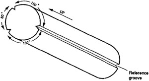
The compass, camera, and timer system is mounted at the top of the inner core barrel, inside a nonmagnetic collar. The battery-driven timer is set prior to running in the hole to expose a frame of film automatically at intervals of 1 to 8 min. Each frame records the compass and the position of a reference mark. As the coring assembly is made up, a lug on the compass is aligned with a reference scribe (one of usually three knives set in a scribe shoe at the base of the inner core barrel) (Figure 2). As the core is cut and enters the mouth of the barrel, grooves are cut in the surface of the core by the scribe knives. Angles between the scribe knives vary between coring companies, but the reference scribe is usually offset from the secondary knives by oblique angles on the order of 130° to 150°. A preferred arrangement is an asymmetric scribe shoe in which the angles from the reference scribe to each of the secondary scribes differs (Figure 2). Such an arrangement allows up-down directions on the core to be distinguished easily.
At agreed upon depth intervals, pumps and rotation are shut down for a period of several minutes to allow for a vibration-free film frame to be snapped. The process is repeated at intervals until the core barrel is tripped out. At the surface, the film is retrieved and developed. The azimuth of the compass lug, and hence of the reference groove, is then determined for the depths at which vibration-free shots were taken. Results can be available at the wellsite within hours of core retrieval. A recent refinement of this system uses a modified measurement while drilling (MWD) unit to replace the camera and timer within the nonmagnetic collar. The unit is powered by a battery pack and records azimuth data continuously. The recorded data are retrieved from the unit when the barrel is tripped out. This system has the advantage that it is not necessary to shut down pumps and rotation to record data.
Core-based orientation techniques
Core-based techniques rely at least in part on data derived from the core for orientation. If bedding planes and fractures can be discerned in the core, it may be possible to use dipmeter logs or data from borehole televiewers to determine the orientation of the core. Another approach to core-based orientation involves analysis of naturally existing paleomagnetic signals in rock to determine their relationship to present-day geographic north.
Paleomagnetic core orientation
The paleomagnetic technique is based on the fact that nearly all rocks, including quartzite, chert, and chalk, contain at least trace amounts of magnetic minerals such as magnetite and hematite. These minerals act as miniature compasses and lock-in the earth's ambient magnetic field. A primary signal is imprinted near the time of deposition; over time, one or more secondary signals may be overlain on the primary signal. In specially equipped laboratories, the signals in rock samples can be separated, interpreted, and used to orient core to present-day geographic north.
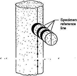
Paleomagnetic core orientation requires that a number of 1-in.-diameter plug samples be collected from the core at the surface (Figure 3). The number of samples required to achieve a good statistical result is dependent on the rock type and other factors. Plugs are then sent to a laboratory for analysis, and core orientation results are typically returned in one to four weeks.
No core-based orientation technique can be considered to give real-time results. In each case, recovered core must be analyzed or sampled. That data, combined with laboratory or borehole information (wireline or televiewer runs) may not be available for days or months.
Advantages and disadvantages of core orientation techniques
Numerous studies have been done to determine the accuracy of different orientation techniques. Nelson et al.[5] provides a particularly comprehensive review of error sources for mechanical orientation and comparisons of accuracy with other techniques. Core orientation techniques are capable of achieving, under optimum conditions, accuracies of ≤5°. Sources and severity of errors depend on many factors, some of which are listed here:
- At high latitudes, most techniques are prone to failure for similar reasons: the inclination of the ambient earth's field makes an accurate measurement of azimuth difficult.
- High angle deviation of a borehole may exacerbate or reduce errors, depending on the direction of deviation. In holes approaching horizontal, orientation of cores to geographic north loses its meaning; up-down core directions then become important.
- During mechanical core orientation, film or batteries can fail under high temperature conditions (generally >temperature::240°F) or film may run out if downhole time is extended. Tandem systems are recommended to reduce the chance of failure.
- Scribe knives may break or be blunted in extremely hard formations; soft or unconsolidated formations may be unsuitable for scribing because the scribe knife may not leave a permanent core groove.
Dipmeter and borehole televiewer
Dipmeters and borehole televiewers must detect formation contrast to be effective orientation tools. Formations that have apparent bedding dips at right angles or parallel to the core axis and limited changes in bedding attitude over the length of the core may not be appropriate for orientation by dipmeter or televiewer. If fractures are absent or abundant, or only at right angles to the core axis, results may also be unusable for orientation. Studies by Hocker et al.[6] offer some indication of the limits of resolution possible using one contemporary dipmeter tool.
Mechanical core orientation
Mechanical core orientation relies on a premeasured relationship being maintained between the compass lug at the top of the core barrel and the reference scribe at the bottom of the core barrel. Depending on barrel length, there are one or more makeup joints between the two components subject to torquing during coring rotation. Furthermore, the grooves in the core tend to precess along the length of the core. Hence, orientation accuracy in part depends on the ability to recognize and quantify these effects. Nelson et al.[5] and Bleakly et al.b[7] describe graphic and overlay techniques as well as wellsite procedures that can be used to recognize and partially correct for such problems.
Paleomagnetic core orientation
Paleomagnetic orientation can be used in hard and soft formations and has been successfully applied under very high temperature conditions in geothermal wells. The technique may not be appropriate in uniformly very coarse grain sands, conglomerates, or brecciated formations. Orientation accuracy is in part dependent on the quantity of magnetic material present in samples; comparatively more samples must be taken from intervals exhibiting very weak magnetic signals. Under some circumstances, collecting a statistically significant number of samples may entail removal of an appreciable portion of the available core.
Core orientation quality
For best results, core orientation technique(s) should be selected on the basis of the operating conditions and the ultimate applications of the results.
Proper core handling can enhance orientation quality regardless of the techniques selected[5][7] (also see “Core handling”). A primary goal of handling procedures is to reconstruct the core as accurately and completely as possible immediately after recovery from the barrel. It is recommended that an asymmetric scribe shoe be used on all core runs to aid reconstruction.
At the well site, cores should be carefully fitted together into continuous intervals, which are defined as lengths of core in which each piece fits into the next. Continuous intervals can vary in length from a few centimeters to length::10 m or more. Intervals are nomally broken by drill string connection points, core rubble zones, core spinoffs, and the tops and bottoms of core runs.
Each continuous interval should be marked with a continuous line or lines parallel to the axis of the core. A right angle straight edge can be used to ensure that this master orientation line (MOL)[8] is parallel to the core's long axis. Placement of an MOL on each interval can be critical to interpretation of orientation results after the core leaves the wellsite. If mechanical orientation has been done, orientation results can be compared against measurements taken on the core, using the MOL as a baseline.[7] For core-based orientation techniques, the MOL can serve as the orientation reference line.
See also
References
- ↑ Pettijohn, F. J., P. E. Potter, and R. Siever, 1973, Sand and sandstone: New York, Springer-Verlag, 618 p.
- ↑ Teufel, L. W., C. M. Hart, A. R. Sattler, and J. A. Clark, 1984, Determination of hydraulic fracture azimuth by geophysical, geological, and oriented core methods at the multi-well experiment site, Rifle, Colorado: Sandia National Laboratories Paper SAND 84-0380, Society of Petroleum Engineers Paper No. 13226, 15 p.
- ↑ Lacy, L. L., 1984, Comparison of hydraulic fracture orientation techniques: Society of Petroleum Engineers Paper No. 13225, 12 p.
- ↑ Rowley, D. S., C. A. Burk, T. Manual, and W. F. Kempe, 1971, Oriented cores: Christensen Diamond Products Paper, 15 p.
- ↑ 5.0 5.1 5.2 Nelson, R. A., L. C. Lenox, and B. J. Ward, 1987, Oriented core—its use, error, and uncertainty: AAPG Bulletin, v. 71, n. 4, p. 357–367.
- ↑ Hocker, C., K. M. Eastwood, J. G. Herweijer, and J. T. Adams, 1990, Use of dipmeter data in clastic sedimentological studies: AAPG Bulletin, v. 74, n. 2, p. 105–118.
- ↑ 7.0 7.1 7.2 Bleakly, D. C., D. R. Van Alstine, and D. R. Packer, 1985b, How to evaluate orientation data, quality control in technology: Oil and Gas Journal, v. 83, n. 49, p. 46–54.
- ↑ Bleakly, D. C., D. R. Van Alstine, D. R. Packer, 1985a, Controlling errors minimizes risk and cost in core orientation in technology: Oil and Gas Journal, v. 83, n. 48, p. 103–110.


