Kerogen
| Exploring for Oil and Gas Traps | |
| |
| Series | Treatise in Petroleum Geology |
|---|---|
| Part | Critical elements of the petroleum system |
| Chapter | Evaluating source rocks |
| Author | Carol A. Law |
| Link | Web page |
| Store | AAPG Store |
Depositional environment is the dominant factor in determining the types of organic matter found in a rock. Only two types of organic matter are found in rocks: land derived and aquatic algae derived. Heat and pressure convert organic matter into a substance called humin and then into kerogen. Time and temperature convert kerogen into petroleum.
What is kerogen?
Geochemists[1][2] define kerogen as the fraction of sedimentary organic constituent of sedimentary rocks that is insoluble in the usual organic solvents. Kerogens are composed of a variety of organic materials, including algae, pollen, wood, vitrinite, and structureless material. The types of kerogens present in a rock largely control the type of hydrocarbons generated in that rock. Different types of kerogen contain different amounts of hydrogen relative to carbon and oxygen. The hydrogen content of kerogen is the controlling factor for oil vs. gas yields from the primary hydrocarbon-generating reactions.
Structured kerogens include woody, herbaceous, vitrinite, and inertinite. Amorphous kerogens are by far the most prevalent and include most of the algal material.
Kerogen quality
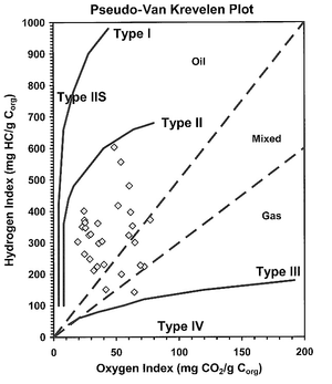
The type of kerogen present determines source rock quality. The more oil prone a kerogen, the higher its quality. Four basic types of kerogen are found in sedimentary rocks. A single type or a mixture of types may be present in a source rock. The table below lists and defines these four basic kerogen types.
| Kerogen type | Predominant hydrocarbon potential | Amount of hydrogen | Typical depositional environment |
|---|---|---|---|
| I | Oil prone | Abundant | Lacustrine |
| II | Oil and gas prone | Moderate | Marine |
| III | Gas prone | Small | Terrestrial |
| IV | Neither (primarily composed of vitrinite) or inert material | None | Terrestrial(?) |
Parameter differences
The table below shows examples of the relationships between hydrocarbon generation zones, maturity, and transformation ratio for standard types II and III kerogens, based on a specific burial and thermal history model. The most significant difference is in the depth to the onset of oil generation, where depth::1000 m separates the top of the oil windows of these two kerogen types.
| Hydrocarbon generation zone | Vitrinite refl., % Ro, Type II | Vitrinite refl., % Ro, Type III | Transformation ratio, %, Type II | Transformation ratio, %, Type III | Present-day depth, m, Type II | Present-day depth, m, Type III |
|---|---|---|---|---|---|---|
| Onset oil | 0.55 | 0.85 | 5 | 12 | 2200 | 3200 |
| Onset peak rate generation | 0.65 | 1.00 | 17 | 31 | 2600 | 3500 |
| Onset gas/cracking liquids | 0.95 | 1.35 | 88 | 64 | 3400 | 4050 |
Transformation ratio
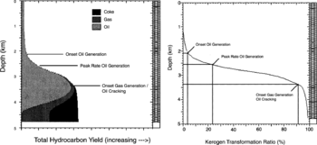
When we compare hydrocarbon generation curves and transformation ratio curves from 1-D models, we can develop a relationship in a way similar to that for generation-maturity. If vitrinite reflectance data are available, the relationship between transformation ratio and maturity can be used to predict (1) percentage of kerogen that has generated hydrocarbons at a given depth and (2) hydrocarbon yields.
Example
Based on Figure 1, we determine that at a depth of length::2.6 km the modeled well is presently in the oil generation zone and approximately 25% of the kerogen in the source rocks at this depth has generated hydrocarbons. We know from the hydrocarbon generation-maturity relationship that at length::2.6 km this well has a vitrinite reflectance ( Ro) of 0.7%. If another well in the basin contains similar source rocks and has a maturity of 0.7% Ro at length::3.7 km, then we can predict that the section at length::3.7 km is mature for liquid generation and has generated a liquid hydrocarbons, converting approximately 25% of its kerogen to hydrocarbons.
Kerogen types
| Source and Migration Processes and Evaluation Techniques | |
| |
| Series | Treatise Handbook |
|---|---|
| Part | Petroleum Generation and Migration |
| Chapter | Petroleum Source Rocks and Organic Facies |
| Author | S. R. Jacobson |
| Link | Web page |
| PDF file (requires access) | |
| Store | AAPG Store |
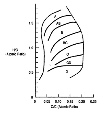
The following descriptions of kerogen types indicate their biological input, stratigraphy, and depositional processes that control their oil-generative properties. Kerogen types are defined on H/C and O/C values (or HI and OI from Rock-Eval). In thermally immature samples, the chemically extreme kerogen types I and IV (and therefore the equivalent organic facies A and D) contain macerals having relatively uniform chemical properties. These end-members are dominated by the most and least hydrogen-rich constituents. Other kerogen types (and therefore their equivalent organic facies) are frequently mixtures of macerals. Microscopy is the method of choice for distinguishing the constituents of mixed organic matter assemblages.
Before enumerating the criteria for discriminating kerogen types, it is important to consider the "mineral matrix effect." Some mineral (polar clay) constituents retard the release of hydrocarbons from powdered whole rock samples during Rock-Eval pyrolysis, under-evaluating the quantity, quality, and thermal maturation data. Although this factor, the mineral matrix effect, is well known to organic geochemists, it is frequently overlooked when interpreting Rock-Eval-dependent values used to determine kerogen type and organic facies. The mineral matrix effect occurs when polar clays react with polar organic molecules during the nonhydrous Rock-Eval procedure.[4][5][6][7][8][9][10][11]
Pioneers of pyrolysis found that some minerals inhibit hydrocarbon expulsion during whole-rock pyrolysis and not during kerogen pyrolysis.[4][5][7] The effect of different matrix constituents[4][5][7][8] varies from strongest to weakest: illite > Ca-bentonite > kaolinite > Na-bentonite > calcium carbonate > gypsum.[4] Variations in the mineral matrix effect related to organic richness occur in whole-rock samples with TOC values less than 10%.[4][5][7]
Geological thermal maturation processes differ from those of Rock-Eval pyrolysis. Whole-rock Rock-Eval samples are heated rapidly in an anhydrous environment. Geological burial processes cause clays to undergo physical and chemical alteration usually preceding the slow and systematic thermal conversion (generation) of kerogen to petroleum. These changes occur in hydrous environments, which probably reduce the reactive capabilities of clays, usually before significant hydrocarbon generation has occurred. Nevertheless, some degree of mineral matrix effect probably does persist under geological conditions.
Kerogen Type I
Kerogen type I is predominantly composed of the most hydrogen-rich organic matter preserved in the rock record. Often the organic matter is structureless (amorphous) alginite and, when immature, fluoresces golden yellow in ultraviolet (UV) light. A large proportion of type I kerogen can be thermally converted to petroleum and therefore is rarely recognizable in thermally mature or postmature rocks. Sometimes in thermally immature rocks, morphologically distinct alginite is structurally or chemically assignable to specific algal or bacterial genera. These organic-walled microfossils have high H/C values because they formed hydrocarbons biologically. Some examples of pure assemblages with type I kerogen properties include the following: (1) the lacustrine alga Botryococcus braunii, which sometimes retains its diagnostic cup-and-stalk colonial morphology and/or its unique chemical compound, botryococcane;[13] (2) Tasmanites spp., which are low-salinity, cool water, marine algal phyto-plankton with unique physical features;[14] and (3) the Ordovician marine organic-walled colonial microfossil Gloeocapsomorpha prisca, with its diagnostic physical appearance and unique chemical signature.[15] Where kerogen type I is widespread, it is mapped as organic facies A. It usually forms in stratified water columns of lakes, estuaries, and lagoons.
Kerogen type I is concentrated in condensed sections where detrital sediment transport is low and primarily pelagic. Condensed sections occur in offshore facies of transgressive systems tracts in marine and lacustrine settings. Although this extension of terminology from marine to lacustrine environments may be unfamiliar at first, lacustrine rocks are formed by the same dynamic processes that form marine rocks (i.e., sediment supply, climate, tectonics, and subsidence), although changes in lake levels often reflect local changes in runoff, evaporation, and sediment basin filling rather than the global and relative sea level changes postulated for marine sediments.[16]
Kerogen Type II
Kerogen type II in its pure (monomaceral) form is characterized by the relatively hydrogen-rich maceral exinite. Examples include spores and pollen of land plants, primarily marine phytoplankton cysts (acritarchs and dinoflagellates), and some land plant components such as leaf and stem cuticles. As with kerogen type I, the occurrence of kerogen type II depends on high biological productivity, ow mineralic dilution, and restricted oxygenation. The pure exinitic kerogen type II is preserved in condensed sections and represents macerals that are slightly less hydrogen rich than kerogen type I.
Kerogen type II can also be formed from partial degradation of type I kerogen or from varying mixtures of type I and types II, III, and IV. For example, organic matter formed in different provenances can be combined, such as when planktonic algal material falls into sediments containing transported woody macerals (kerogen type III). Kerogen type II is recorded in transgressive systems tracts, sometimes landward of type I kerogen deposition.
Kerogen Type III
Kerogen type III contains sufficient hydrogen to be gas generative but not enough hydrogen to be oil prone. In its pure form, it is composed of vitrinite, a maceral formed from land plant wood. As with other intermediate kerogen types, however, various maceral mixtures or degradational processes can contribute to kerogen type III formation. Coal-forming environments represent several different kerogen types. Most coals form in paralic swamps and abandoned river channels. Vail et al. (in press) find that in regions where sediment supply is low, incised valleys contain these sediments as estuarine or coastal plain deposits.
Kerogen Type IV
Kerogen type IV is a term not universally employed by organic geochemists because it is difficult to distinguish type IV from type III using only Rock-Eval pyrolysis. It is an inert (does not generate hydrocarbons) end-member on the hydrocarbon generative spectrum. Kerogen type IV is composed of hydrogen-poor constituents such as inertinite, which is detrital organic matter oxidized directly by thermal maturation including fire (charcoal) or by biological or sedimentological recycling.
See also
- Rock Eval analysis using hydrogen index (HI) and oxygen index (OI)
- Kerogen type and quality: visual assessment
- Pyrolysis gas chromatography
- Relationships between maturity and hydrocarbon generation
- Kerogen type and hydrocarbon generation
- Kerogen type and maturity
- Kerogen type and transformation ratio
- Open- vs closed-system generation modeling
- Van Krevelen diagram
- Type I kerogen
- Type II kerogen
- Type IIS kerogen
- Type III kerogen
- Type IV kerogen
References
- ↑ Durand, B., 1980, Sedimentary organic matter and kerogen: definition and quantitative importance of kerogen, in B. Durand, ed., Kerogen: Techniq, p. 13–14.
- ↑ Tissot, B. P., and D. H. Welte, 1984, Petroleum Formation and Occurrence, 2 ed.: New York, Springer-Verlag, 699 p. The best overall reference for petroleum geochemistry.
- ↑ Dembicki, H., 2009, Three common source rock evaluation errors made by geologists during prospect or play appraisals: AAPG Bulletin, vol. 93, issue 3, pp. 341-356.
- ↑ 4.0 4.1 4.2 4.3 4.4 Espitalie, J., M. Madec, and B. Tissot, 1980, Role of mineral matrix in kerogen pyrolysis: Influence on petroleum generation and migration: American Association of Petroleum Geologists Bulletin, v. 64, p. 59-66.
- ↑ 5.0 5.1 5.2 5.3 Horsfield, B., and A. G. Douglas, 1980, The influence of minerals on the pyrolysis of kerogens: Geochimica et Cosmochimica Acta, v. 44, p. 1110-1131.M
- ↑ Orr, W. L., 1983, Comments on pyrolitic hydrocarbon yields in source-rock evaluation, in M. Bjoroy et al., eds., Advances in Organic Geochemistry 1981, p. 775-787.
- ↑ 7.0 7.1 7.2 7.3 Dembicki, H., B. Horsfield, and T. Y. Ho, 1983, Source rock evaluation by pyrolysis-gas chromatography: American Association of Petroleum Geologists Bulletin, v. 67, p. 1094-1103.
- ↑ 8.0 8.1 Katz, B. J., 1983, Limitations of Rock Eval pyrolysis for typing organic matter: Organic Geochemistry, v. 4, p. 195-199.
- ↑ Peters, K. E., 1986, Guidelines for evaluating petroleum source rocks using programmed pyrolysis: American Association Petroleum Geologists Bulletin, v. 70, p. 318-329.
- ↑ Crossey, L. J., E. S. Hagan, R. C. Surdam, and P. W. Lapointe, 1986, Correlation of organic parameters derived from elemental analysis and programmed pyrolysis of kerogen: Society of Economic Paleontologists and Mineralogists, p. 36-45
- ↑ Langford, F. F., and M. M. Blanc-Valleron, 1990, Interpreting Rock-Eval data using graphs of pyrolizable hydrocarbons vs. total organic carbon: American Association Petroleum Geologists Bulletin, v. 74, p. 799-80
- ↑ Jones, R. W., 1987, Organic Facies, in J. Brooks and D. H. Welte, eds., Advances in Petroleum Geochemistry, v. 2, Academic Press, London, p. 1-90.
- ↑ Moldowan, J. M., and W. K. Seifert, 1980, First discovery of botryococcane in petroleum: Chemical Communications, v. 34, p. 912-914.
- ↑ Prauss, M., and W. Riegel, 1989, Evidence from phytoplankton associations for causes of black shale formation in epicontinental seas: Neues Jahrbuch fur Geologie und Palaontologie, Monatshefte, v. 11, p. 671-685.
- ↑ Reed, J. D., H. A. Illich, and B. Horsfield, 1986, Biochemical evolutionary significance of Ordovician oils and their source: Organic Geochemistry, v. 10, p. 347-358.
- ↑ Haq, B. U., J. Hardenbohl, and P. K. Vail, 1988, Mesozoic and Cenozoic chronostratigraphy and cycles of sea-level Change, in C. K. Wilgus et al., eds., Sea-Level Changes: An Integrated Approach, SEPM Special Publication 42, p. 71-108.