Measurement while drilling
| Development Geology Reference Manual | |

| |
| Series | Methods in Exploration |
|---|---|
| Part | Wellsite methods |
| Chapter | Measurement while drilling |
| Author | Michael F. Medeiros |
| Link | Web page |
| Store | AAPG Store |
Measurement while drilling (MWD) technology provides downhole evaluation of formation gamma ray, resistivity, and porosity while drilling is in progress. Mechanical parameters such as the following are also measured and recorded for well surveillance:
- Well deviation and azimuth
- Rate of penetration (ROP)
- Weight and torque on bit
Data acquisition

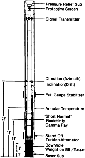
Downhole MWD hardware consists of sensors built into a drill collar positioned near the bit (Figure 1). Electrical energy for the system is provided by a battery pack or generated by a small turbine.
In a battery pack MWD system, information is recorded and stored downhole in the microprocessor. The data are retrieved when the MWD collar is brought to the surface and are transferred to the computer in the logging unit for additional processing.
In a typical turbine-powered “real time” MWD system, data are sent directly to the surface by mud telemetry, which utilizes the column of fluid inside the drill pipe as a transmission line for digital acoustic signals. Downhole measurements recorded by the sensors are transmitted through the mud as positive or negative pressure pulses or as a continuous, fixed-frequency pressure wave.
The mud telemetry signals are detected with pressure transducers in the standpipe. The digital signals are then recorded by a computer. Data are converted to engineering units and processed to generate depth- or time-based output.
Data display
At the wellsite, information is displayed on video monitors located in the logging unit or at other locations around the rig. Real time MWD data can also be transmitted via telephone modem to a remote location where drilling progress can be monitored by the development geologist, engineering personnel, and management.
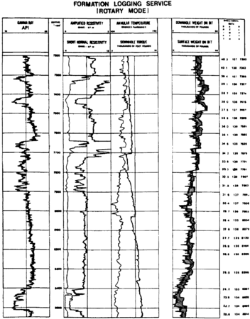
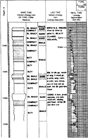
Hardcopy directional plots and well logs can be produced at specified scales and annotated with mechanical and geological information (Figures 2 and 3).
Applications
Measurement while drilling technology has become an important tool for reservoir evaluation in the past 10 years. Gamma ray, resistivity, and porosity logs obtained during drilling are commonly being used to supplement or replace wireline logs for formation evaluation and geological correlation in high risk or high cost operations.
Formation evaluation
Formation evaluation using MWD technology has several advantages over conventional wireline log methods:
- Because MWD measurements are made soon after the interval has been penetrated by the bit, the effects of invasion fluids are reduced. By minimizing the effects of invasion, a more reliable evaluation of critical formation properties can be achieved.
- In directionally drilled wells, where hole angles can deviate as much as 80° from vertical, wireline logs are often difficult and very costly to obtain. In these situations, MWD data may provide the only permanent record of the borehole. MWD logs also provide “insurance” in the event a well must be abandoned due to mechanical reasons.
- The electrode spacing and slower penetration rate of the MWD tool provide a larger number of samples per foot. The increased sample density often results in better resolution of thin beds, particularly with electromagnetic propagation resistivity tools. Because the logging speed is dependent on the rate of penetration, drilling can be controlled through zones of interest to obtain maximum resolution.
Geological correlation
Prior to MWD technology, drilling time plots or rate of penetration (ROP) plots were used for geological correlation while drilling was in progress. These plots can be difficult to use, particularly in complex areas, because penetration rate can be controlled by mechanical parameters. With a MWD gamma ray or resistivity log, correlation with offset wells is much more reliable.
Measurement while drilling logs have been used successfully for geological correlation by providing the following functions:
- Determination of coring points—Prediction of lithology ahead of the bit is critical when selecting prospective intervals for coring. With MWD log data, the geologist can obtain a more reliable correlation and can select core points with more confidence. This reduces the risk of missing critical formation tops or coring intervals that are not essential for geological or reservoir evaluation.
- Selection of optimum casing and total well depths— Accurate and timely selection of casing and total well depth become extremely important when the possibility of penetrating abnormally pressured zones exists. This condition often requires extra rig time to circulate and condition the drilling mud or, in the worst case, results in drill pipe sticking and expensive fishing operations.
- Determination of kick-off point(s) for sidetrack wells—The decision to sidetrack or redrill a well to a more favorable location can be made immediately if MWD data show the objective section to be poorly developed, faulted out, or drained. This often results in considerable cost savings by preventing unnecessary drilling below the objective interval and by eliminating the need for wireline logs.
- Determination of kick-off point(s) for horizontal wells— MWD logs are used for correlation with offset data and for directional planning in complex horizontal wells. With real time information obtained near the bit, borehole deviation and azimuth are continuously monitored and corrected to obtain the optimum angle of penetration. This helps ensure that the horizontal wellbore stays on target and within the desired reservoir interval.
- Aid in “steering” highly deviated and horizontal wells— Using a real time MWD system, the geologist and field personnel can monitor the well path as the objectives are penetrated. The geologist is therefore better equipped to make important cost-saving decisions and provide management with the most recent interpretation and well strategy.

