Production testing
| Development Geology Reference Manual | |

| |
| Series | Methods in Exploration |
|---|---|
| Part | Production engineering methods |
| Chapter | Production testing |
| Author | David E. Lancaster |
| Link | Web page |
| Store | AAPG Store |
Production tests are run to obtain an indication of well productivity. Some production tests are performed in open hole (such as drill stem tests) and can be used in making completion decisions. Others (such as single-point, multipoint, and swab tests) are performed after the well is completed and generally involve routine measurements of oil, gas, and/or water production under normal producing conditions. The test results can be used to determine reservoir properties, to assess the degree of damage or stimulation, to identify production and reservoir problems, or to satisfy the reporting requirements of regulatory bodies. Production tests can also be performed when more conventional well tests (such as pressure drawdown and buildup tests) are impractical due to time constraints, well conditions, or extremely low well productivity.
Drill stem tests[edit]

Drill stem tests (DSTs) are used to obtain (1) samples of the reservoir fluid, (2) measurements of static bottomhole pressure, (3) an indication of well productivity, and (4) short-term flow and pressure buildup tests from which permeability and the extent of damage or stimulation can be estimated.[2] A DST is run in the open hole after drilling, and is often used in deciding whether to complete a particular zone. The total test duration is frequently a function of hole condition, and the tool assembly must be retrieved from the open hole after the test is completed (see Drill stem testing).
To run a drill stem test, a special DST tool is attached to the drill pipe and run in the hole opposite the zone to be tested. A DST tool typically includes two or more clock-driven, bourdon-tube recording pressure gauges, a set of flow valves, and one or two packers. The tool isolates the formation from the mud column in the annulus. When the tool is opened, reservoir fluid can flow into the drill pipe (and possibly to the surface); pressure is recorded continuously during the test.
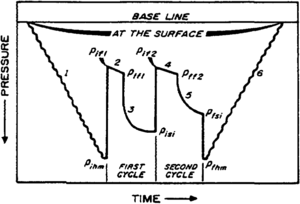
Most DSTs (Figure 1) consist of two flow periods and two shut-in periods. The pressure gauges record the initial hydrostatic mud pressure (pihm) while going into the hole. The initial flow period (pifl to pffl) is a short production period, usually only 5 to 10 min. Pressure rises during the flow period as fluid collects in the drill stem above the pressure gauges. The objective is to release the hydrostatic mud pressure and draw down the formation pressure only slightly. The first shut-in period (pffl to pisi) should be long enough to allow the reservoir pressure to return to its initial value. A shut-in time of 1 hour is usually preferred.
In the second flow period (pif2 to pff2), the objective is to capture a large sample of formation fluid and to reduce the pressure as far into the reservoir as possible. This flow period should be at least 1 hour, and if reservoir fluid is produced to the surface, flow rates should be measured. The second shut-in period (pff2 to pfsi) is longer than the first and is used to estimate formation properties in a manner similar to that for analyzing conventional buildup tests. The duration of the final shut-in period depends on well behavior during the flow test; it may range from one-half to twice the flow time. Comparison of the final or extrapolated reservoir pressure from this second shut-in period to that from the initial shut-in period may suggest depletion has occurred during the DST. If so, the zone being tested is a limited, noncommercial reservoir. Following the second shut-in period, the final hydrostatic mud pressure is measured (pfhm) and the DST tool is pulled from the hole.
Single-point tests[edit]
Single-point tests are usually simple productivity tests that typically involve a measurement (or estimate) of initial or average reservoir pressure and a measurement of flow rate and flowing bottomhole pressure (which can be estimated from flowing surface pressure) at stabilized producing conditions.[3] From these data, the productivity index, PI, can be calculated as follows:
where
- q = flow rate (STB/day or MSCF/day)
- = initial or current average reservoir pressure (psia)
- pwf = flowing bottomhole pressure (psia)
- μ = viscosity (cp)
- B = formation volume factor (rcf/MSCF)
The productivity index can be a useful indicator of well productivity and wellbore condition during the life of a well. PI will generally decrease over time due to declining reservoir pressure, changes in producing conditions, and/or production problems.
Single-point tests can also be used to estimate formation permeability[4] with an iterative solution of the transient radius of drainage equation (Equation 2) and the pseudosteady-state flow equation (Equation 3), as follows:
where
- rd = transient radius of drainage (ft)
- k = permeability (md)
- t = flow time (hr), generally best estimated by dividing cumulative fluid production by flow rate, q
- ϕ = porosity (fraction)
- ct = total compressibility (psia–1)
- B = formation volume factor (rb/STB for oil or rb/MSCF for gas)
- rw = wellbore radius (ft)
- h = net pay (ft)
- s′ = apparent skin factor
To solve for permeability, an arbitrary value of permeability is assumed (0.1 md is often a good first estimate), and Equation 2 is solved for rd. Then, this value for rd is used in Equation 3 to solve for permeability. For each iteration after the first, use the permeability calculated from Equation 3 in solving for rd from Equation 2; this procedure usually converges in three to four iterations.
The need to estimate an apparent skin factor, which is usually not known, is the biggest limitation of this method. Pressure buildup tests run in other wells in the same reservoir often provide a good estimate of typical skin factors. Low permeability wells are generally broken down and balled out after completion and prior to testing; in these wells, a skin factor of –1 to –2 is often a reasonable assumption. If a well has been damaged by drilling fluids and the perforations have not been broken down, a skin factor of +2 to +5 (or more) is appropriate (see Fluid flow fundamentals).
The single-point test method for estimating permeability is valid for constant flow rate production, constant bottomhole pressure production, or smoothly changing bottomhole pressures and flow rates. The method is recommended for estimating permeability from prefracture flow test data only; it does not work well with postfracture flow data. The method is particularly useful in low permeability reservoirs where operators do not run buildup tests routinely because of the long test times required to overcome wellbore storage effects and reach radial flow (see Pressure transient testing).
Multi-point tests[edit]
Multi-point tests are typically used to establish gas well deliverability and absolute open flow potential; these tests may also be referred to as gas well deliverability tests, backpressure tests, or flow-after-flow tests.[3] Multi-point tests typically require the measurement of gas flow rates and surface pressures at four stabilized flow conditions; surface shut-in pressure is also measured. Generally, an increasing flow rate sequence is preferred to a decreasing rate sequence.
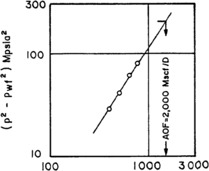
The surface shut-in and flowing pressure measurements are converted to bottomhole conditions and a log-log plot of versus flow rate, q, is generated (Figure 2). The four points define a straight line with a slope that is generally between 0.5 and 1.0. This straight line is extrapolated to determine gas flow rate at a point where the flowing bottomhole pressure is zero; this rate is referred to as the absolute open flow (AOF) potential of the well.
Multi-point test data can also be used to estimate permeability using a variable rate flow test analysis.[5] For gas wells, the data are plotted as
where
- pwfn = flowing bottomhole pressure at time tn (psia)
- qn = last of n different flow rates (MSCF/day)
- Δqj = qj+1 – qj (MSCF/day), qo=0
- tn = total (cumulative) flowing time for n constant rate flow periods (hr)
- tj = time at which flow rate was changed (hr)
The plot is made on Cartesian coordinate paper. A straight line with slope, m′, should result; this slope is used in Equation 4 to calculate permeability:
where
- z = real gas compressibility factor
- T = reservoir temperature (°R)
The apparent skin factor can also be determined from this plot. If the intercept of the plot (the value of Δp2/q where the time plotting function is zero) is denoted by b, then
Since multi-point test data are available for virtually all gas wells, this method of analysis often proves to be a useful way of estimating permeability and skin factor, especially when drawdown or buildup tests are not available.
Swab tests[edit]
Swabbing can be defined as pulling a full-diameter tool from the wellbore; this pulling action is similar to that of a plunger in a syringe, and it initiates fluid flow into the wellbore.[6] On occasion, oil or gas wells may not flow fluid to the surface on completion. When this occurs, a swabbing unit is run to remove the hydrostatic column of fluid in the wellbore and allow the well to kick off and flow.
In some oil wells, the bottomhole pressure may be insufficient to lift fluid continuously. Because a surface flow rate cannot be maintained and measured, routine flow and buildup tests cannot be used to evaluate reservoir properties and determine well productivity. In these instances, a swabbing tool can be run at regular intervals to keep fluid flowing from the formation more or less continuously.
By carefully recording the volume of fluid recovered from each swabbing run as a function of time, one can determine the rate of fluid feed-in from the formation to the wellbore. These data can then be used to estimate well productivity or formation permeability using the methods outlined in the discussion of single-point tests. The information gained from a swabbing test can also be particularly useful in determining whether a pumping unit should be installed on a well and in determining the proper pump design.
See also[edit]
- Production histories
- Artificial lift
- Surface production equipment
- Stimulation
- Introduction to production engineering methods
- Pressure transient testing
- Well completions
- Production logging
- Production problems
- Workovers
References[edit]
- ↑ Earlougher, R. C., Jr., 1977, Advances in Well Test Analysis: Dallas, TX, American Institute of Mining, Metallurgical and Petroleum Engineers, Society of Petroleum Engineer's Monograph 5, 264 p.
- ↑ Lee, W. J., 1982, Well Testing: Dallas, TX, Society of Petroleum Engineers of AIME, 159 p.
- ↑ 3.0 3.1 Allen, T. O., and A. P. Roberts, 1978, Production Operations, Volume 1: Tulsa, OK, Oil and Gas Consultants International, 225 p.
- ↑ Lee, W. J., T. B. Kuo, S. A. Holditch, and D. A. McVay, 1984, Estimating formation permeability from single-point flow data: Proceedings of the 1984 SPE/DOE/GRI Unconventional Gas Recovery Symposium, Pittsburgh, PA, p. 175–186.
- ↑ Odeh, A. S., and L. G. Jones, 1965, Pressure drawdown analysis, variable-rate case, in Pressure Analysis Methods: Dallas, TX, American Institute of Mining, Metallurgical and Petroleum Engineers, Society of Petroleum Engineers Reprint Series No. 9, 256 p.
- ↑ Whittaker, A. H., 1987, Mud logging, in Bradley, H. B., ed., Petroleum Engineering Handbook: Richardson, TX, Society of Petroleum Engineers.
External links[edit]
- Original content in Datapages
- Find the book in the AAPG Store
- Dictionary:Production testing in Sheriff's Encyclopedic Dictionary


![{\displaystyle k={\frac {141.2q\mu B}{h({\bar {p}}-p_{\rm {wf}})}}\left[\ln \left({\frac {r_{\rm {d}}}{r_{\rm {w}}}}\right)-{\frac {3}{4}}+s'\right]}](https://wikimedia.org/api/rest_v1/media/math/render/svg/0d49f87cc368e123e628311380f88d49a774fb04)


![{\displaystyle s'=1.151\left[{\frac {b}{m'}}-\log \left({\frac {k}{\phi \mu c_{\rm {t}}r_{\rm {w}}^{2}}}\right)+3.23\right]}](https://wikimedia.org/api/rest_v1/media/math/render/svg/7f02ce81dfc4c5f9c35b0464c88fbf17edb46ab6)