Vertical and lateral seismic resolution and attenuation
| Development Geology Reference Manual | |

| |
| Series | Methods in Exploration |
|---|---|
| Part | Geophysical methods |
| Chapter | Vertical and lateral seismic resolution and attenuation |
| Author | R. E. Sheriff |
| Link | Web page |
| Store | AAPG Store |
Vertical resolution
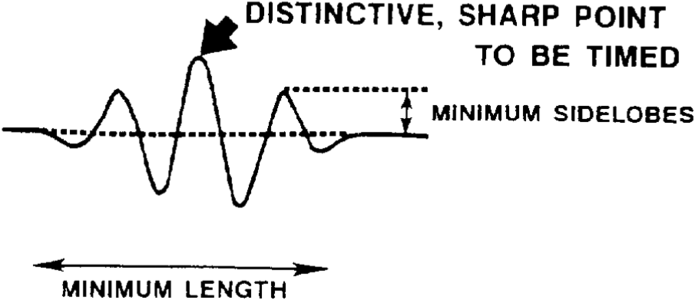
Figure 1 Desired wavelet for positive reflection.
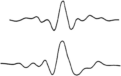
Figure 2 A 1.5-octave zero-phase wavelet passing frequencies between 14 and 65 Hz that passes 100% between 22 and 55 Hz (top), and an embedded wavelet actually achieved (bottom).


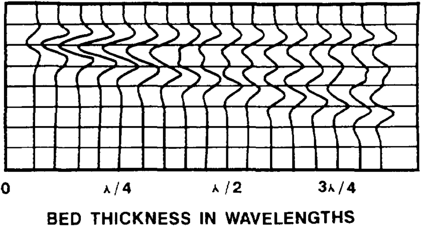
Figure 3 Seismic response of a wedge pinchout.
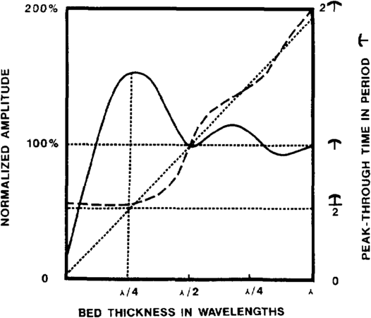
Figure 4 Amplitude (solid line) and time thickness (dashed for observed, dotted for actual) for a 1.5-octave wavelet reflected from the wedge.


Resolution is the ability to distinguish between objects, that is, to see a second object in the presence of another. Concerning seismic data, vertical resolution relates to how far apart two interfaces must be to distinguish separate reflections from them or how thick a bed must be to allow distinguishable reflections from the bed's top and bottom. The length (in time) of seismic wavelets produces confusion because successive reflections overlap, so it is desirable that the source wavelet (Figure 1) be short. The wavelet should have a distinctive, sharp peak to be timed. Side lobes are undesirable because they can be mistaken for true reflections. They add to confusion because of interference. The wavelet that is naturally embedded in the data can be replaced in data processing by a different more desirable wavelet to facilitate interpretation, a procedure usually called wavelet processing. To achieve the desired characteristics, the embedded wavelet (Figure 2) needs a broad spectral range (1.5 octaves) including high frequency content, and the phase response should be zero phase. Data quality, the mode of display, and the interpreter's experience are also clearly factors in being able to resolve reflections.
Assuming that the three foregoing conditions have been met, let's examine a simple model of a very gentle wedge for which the physical properties above and below the wedge are the same (Figure 3). This might represent the pinchout of a sand body embedded in shale or any other combination of lithologics. When the wedge is thick, the reflections from the top and base of the wedge are distinct, and timing of their separation gives the wedge thickness (Figure 4). As side lobes begin to interfere, amplitude begins to change and minor timing errors result. As the wedge thickness approaches one-fourth of a wavelength, constructive interference produces an amplitude buildup known as the tuning effect. The finite frequency of the wavelet will not let the peaks and troughs representing the two reflections come closer, that is, the time separation becomes constant and it is no longer a measure of the wedge thickness. The tuning thickness is usually taken as the limit of resolution or limit of separability. Since wavelength equals velocity divided by frequency, this one-fourth wavelength represents about length::25 ft for moderately shallow beds having a velocity of about 6000 ft/sec for a wavelet with 60-Hz dominant frequency, or about length::250 ft for a deep bed with 15,000 ft/sec velocity and a 15-Hz wavelet. Resolution decreases rapidly with depth because velocity increases and frequency decreases.
Horizontal resolution
The waves giving rise to a reflection event are reflected from a fairly large, roughly circular area of the reflecting interface known as the first Fresnel zone. Reflections from this zone arrive at a geophone so as to constructively interfere. The radius of this zone is often taken as the horizontal resolution for unmigrated seismic data. (A nomogram for Fresnel zone calculation is given by Sheriff.)[1] For the 60-Hz wavelet at 6000 ft/sec previously mentioned, this radius would be about length::500 ft at a depth of depth::5000 ft. As with the wavelength, the Fresnel zone size also increases rapidly with depth.
Seismic migration effectively collapses the in-line aspect of the Fresnel zone, so this measure of resolution is not appropriate with the migrated seismic data that are usually used for interpretation. In principle, after migration, horizontal resolution is reduced to trace spacing. However, migration smears out noise, including contributions from events to the side of the line, and this often becomes the limiting factor. Other factors contributing to limit the horizontal resolution include uncertainty in the velocity and the mathematical completeness of the migration algorithm. One of the most important limitations results from the spatial sampling because of the geophone group interval. At least two samples per wavelength are required by sampling theory to prevent aliasing. An aliased signal appears in the seismic record at lower frequency and/or dip than is real. This yields an equation relating the geophone group interval s to the frequency f and the maximum reflection dip d (in milliseconds per unit of distance) that can be properly imaged:

For a 300-ft group interval and a 50-Hz frequency, dips greater than 0.07 msec/ft are aliased (or 11° for a velocity of 6000 ft/sec). Other considerations are also involved, but clearly many situations require shorter geophone group intervals than commonly used.
Attenuation
The amplitude of seismic waves decreases with seismic traveltime (or depth) because of a number of factors.[2] Seismic processing endeavors to correct for these factors so that amplitude is proportional to reflectivity. However, enough information about all the amplitude-changing factors is never available, so relative amplitude preservation means that gain changes slowly in the same way for every trace. The objective is to preserve the lateral significance of amplitudes so that as one follows a reflection event, changes in amplitude will be proportional to changes in reflectivity. However, the amplitudes of different events may not be proportional to their respective reflectivities.
The earth filters out higher frequencies as a seismic wave travels. This causes a lowering of frequency content with time on seismic records, which in turn causes changes in wave shape. Thus, shallow reflections often have dominant frequencies around 60 Hz, whereas 15 to 20 Hz is usually the dominant frequency for deep reflections. Q-compensation is sometimes applied in processing to compensate partially for the loss of high frequencies with time.
See also
- Seismic interpretation
- Synthetic seismograms
- Forward modeling of seismic data
- Displaying seismic data
- Three-dimensional seismic method
- Seismic data - mapping with two-dimensional data
- Seismic inversion
- Checkshots and vertical seismic profiles
References
- ↑ Sheriff, R. E., 1980, Nomogram for Fresnel-zone calculation: Geophysics, v. 45, p. 968–973, DOI: 10.1190/1.1441101.
- ↑ Sheriff, R. E., 1975, Factors affecting seismic amplitude: Geophysical Prospects, v. 23, p. 125–138, DOI: 10.1111/gpr.1975.23.issue-1.
External links
| find literature about Vertical and lateral seismic resolution and attenuation |