Water resistivity determination
| It has been suggested that some portions of this article be split into multiple articles. |
The most direct way of finding water resistivity (Rw) is to obtain a sample of formation water and measure its resistivity. However, this is seldom possible in practice, as formation water samples, if available, are invariably contaminated by mud filtrate. Rw is therefore usually calculated, and there are three methods available for this purpose:
- SP method
- Archie equation
- Resistivity ratio method
SP method[edit]
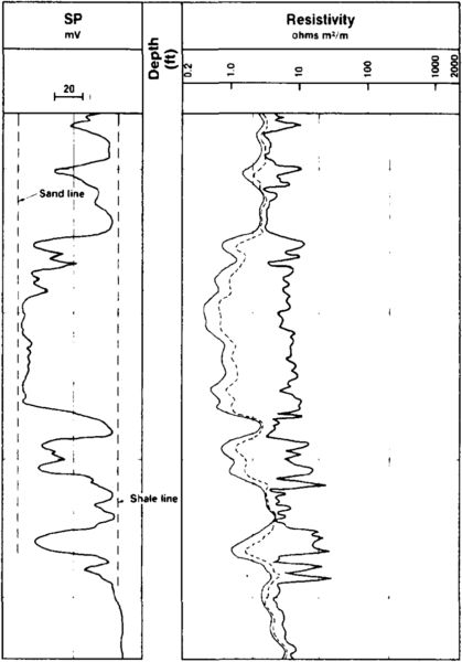
Figure 1 Example of a normal SP deflection. Copyright: Schlumberger Educational Services, 1987.
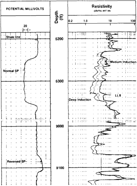
Figure 2 Example of a reverse SP deflection.[1]


Principle[edit]
The first step in the interpretation of the SP log is the establishment of “sand” and “shale” lines, as shown in Figure 1. These are arbitrary limits, with the sand lines normally representing the maximum deflection to the left and shale lines representing the maximum deflection to the right (in shales). Deflections to the left of the shale line are regarded as normal or negative, and correspond to porous and permeable zones containing a more saline interstitial water than the drilling mud (Rw Rmf).
If the mud is more saline than the formation water, the SP currents flow in the opposite direction and the corresponding deflection will be to the right of the shale line. Such a deflection is considered to be reversed or positive (Figure 2). If there is no salinity contrast between the mud and the formation water, no SP currents are generated and no deflection will be observed (SP = 0).
The magnitude of deflection from the shale base line to the maximum deflection developed in a thick, clean, waterbearing sand is referred to as the static SP, or SSP.
Knowledge of the SSP is essential for the derivation of Rw, which is required for the calculation of water saturation in the uninvaded zone. The equation that relates the SSP to measurable quantities, namely, Rw and Rmf, introduces values that are linearly related to their respective chemical activities. These values are referred to as equivalent resistivities and are denoted by Rwe and Rmfe. Thus, the standard equation that relates the SSP to the mud filtrate and uninvaded formation water resistivities is

where K is a constant, the value of which is dependent on the formation temperature. Usually,

Equation 1 is used in the quantitative interpretation of the SP log.
Procedure[edit]

The procedure to determine Rw from the SP is outlined as follows. The data required include the SP, the invaded zone resistivity, the formation temperature, and the mud and mud filtrate resistivities at the given formation temperature.
- After selecting on the log the zone in which water resistivity will be determined, the formation temperature is established and the values of mud and mud filtrate resistivity are corrected accordingly.
- The shale and sand lines are established, the bed boundaries on the SP curve are determined, and maximum SP inflection for that permeable bed are read off the log.
- If the bed was too thin for the SP to develop fully (beds thinner than 20 ft), the appropriate correction is applied from the charts.
- Charts supplied by logging companies permit the determination of Rmfe/Rwe from the SP and, from that, Rwe.
- Finally, the true value of Rw is derived from its equivalent Rwe value, again using the appropriate charts.
An example of calculating Rw by using the SP method is as follows. Figure 3 shows the log used in this example. The following charts are required:
| Schlumberger 1989 | Western Atlas 1985 | |
|---|---|---|
| Chart 1 | GEN-6 | 1-1 |
| Chart 2 | GEN-9 | 1-5 |
| Chart 3 | SP-3 | 2-1 |
| Chart 4 | SP-1 | 2-2 |
| Chart 5 | SP-2 | 2-3 |
Given:
- Rm = 2.5 Ω-m at temperature::70°F
- Rmf = 2.0 Ω-m at temperature::70°F
- Hole diameter = 8 in.
- Surface temperature = temperature::60°F
- BHT = temperature::164°F at 10,500 ft
From the log:
- SP deflection = 70 mV
- Bed thickness = 24 ft
- Short normal resistivity = 65 Ω-m
Calculations:
- Bed is from 8114 to depth::8138 ft.
- From Chart 1, using BHT = temperature::164°F at depth::10,500 ft and surface temperature = temperature::60°F: formation temperature Tf at 8100 ft=temperature::140°F.
- From Chart 2, using Rm = 2.5 Ω-m at temperature::70°F and Rmf = 2.0 Ω-m at temperature::70°F: Rm = 1.3 Ω-m at temperature::140°F and Rmf = 1.0 Ω-m at temperature::140°F.
- Shale baseline is two divisions left of depth column.
- Bed thickness is 8138 to depth::8114 ft = length::24 ft.
- SP deflection =–70 mV.
- Use Chart 3 to correct the SP. Use short normal resistivity, RSN, for invaded-zone resistivity, Ri. This gives Ri/Rm = RSN/Rm = 65/1.3 = 50. This SP correction factor is 1.07, giving a corrected SP of 1.07 × –70 = –75 mV.
- From Chart 4, using SP corrected and Tf: Rmf/Rwe = 9.7.
- Rwe = Rmf/(Rmf/Rwe) = 1.0/9.7 = 0.103 Ω-m.
- From Chart 5, using Rwe and Tf. Rw = 0.103 Ω-m at temperature::140°F (no change).
Assumptions and limitations[edit]
It is assumed that ail salts in solution in the fluids are NaCl or equivalent and that the beds are clay free. This method does not work for oil-based muds. Also, it does not give correct estimations of Rw in hydrocarbon-bearing zones.
Archie equation[edit]
Principle[edit]
If a clean, water-bearing zone is present or can be assumed, Rw can be calculated by using the Archie equation. The zone or permeable bed in which water resistivity is determined is selected on the log. This zone must be 100% water saturated and must not contain any clay or shale. The bed must be thick so that the deep investigation resistivity device is not affected by shoulder beds.
The water saturation equation in general form is

Let's assume for a, m, and n the usual initial values of 1, 2, and 2, respectively (although other values for a, m, and n may be more appropriate). We have

In a water zone, Sw = 1, thus Equation 4 becomes

Porosity (ϕ) can be derived from logs. (For more information on methods to derive porosity and the Archie equation, see Standard interpretation. For more on deriving Rt, see Preprocessing of logging data.)
Procedure[edit]
The procedure to determine Rw from the Archie equation is outlined as follows. The data that are required include Rt (or Ro) from deep-reading resistivity tools such as deep induction (ILd) or deep laterolog (LLd) and porosity log(s).
- After correlating logs for depth mismatch, a clean, water-bearing zone is located. If using an induction log, the minimum thickness should be length::15 ft. For a laterolog, the minimum thickness should be length::4 ft.
- Read Ro (= Rf) from the resistivity log, and determine the porosity from logs or otherwise.
- Calculate Rw from Equation (4a).
Assumptions and limitations[edit]
It is assumed that there are no clay or conductive minerals in the water-bearing zone, that the zone is clean, and that the invasion is shallow enough for resistivity tools to be unaffected by it. This method only works in clean, waterbearing reservoirs. It is typically unreliable in highly fractured or vuggy reservoirs.
Resistivity ratio method[edit]
Principle[edit]
In a clean, water-bearing zone, the following relationships can be obtained from application of the Archie equation in the uninvaded and invaded zones:


In such a zone, Sw = Sxo = 1 and a and ϕ are the same in both the flushed and uninvaded zones.
Dividing Equation 5 by Equation 6 gives

or

Rt and Rxo are obtained from deep and shallow resistivity logs, and Rmf is at formation temperature.
Procedure[edit]

The procedure for determining Rw from the resistivity ratio method is outlined as follows. The data that are required include Rt from ILd or LLd, Rxo from SFL or another shallow-reading resistivity device, Rmf, and Tf.
- After correlating logs for depth mismatch, locate a clean, water-bearing zone. If using an induction log, the minimum thickness should be length::15 ft. For a laterolog, the minimum thickness should be length::4 ft.
- Read Rt and Rxo.
- Correct Rmf to the appropriate formation temperature (Tf) value.
- Calculate Rw from Equation 8.
Note that an equivalent “quick look” solution can be obtained by an overlay technique using logarithmically scaled Rt and Rxo logs. If one log is placed over the other and shifted so that the two curves coincide in clean, water-bearing zones, the 1 ohm-m line on the Rxo log grid will lie on the Rt grid at a value equal to Rw/Rmf. Since Rmf is known, Rw can then be easily calculated. Figure 4 shows an example of original and shifted logs indicating a Rt/Rmf ratio of 0.45.
Limitations[edit]
This method is unreliable in fractured or vuggy reservoirs. It requires a reliable measurement of Rxo. Results can be questionable if the mud resistivity properties have varied significantly after drilling the zone to be analyzed.
Concluding remarks[edit]
It is quite common and good practice to determine Rw with more than one method, if possible, to check for consistency and reliability. Variations may occur in the Rw values determined by the three methods outlined here. If this is the case, then the values obtained can be averaged. Once determined, Rw is assumed to be constant throughout the formation being evaluated, unless local knowledge or clear SP log amplitude changes indicate otherwise.
See also[edit]
- Difficult lithologies
- Dipmeters
- Formation evaluation of naturally fractured reservoirs
- Basic open hole tools
- Basic tool table
- Introduction to wireline methods
- Preprocessing of logging data
- Wireline formation testers
- Basic cased hole tools
- Standard interpretation
- Quick-look lithology from logs
- Borehole imaging devices
References[edit]
External links[edit]
| find literature about Water resistivity determination |