In-situ stress characterization and applications
| Wiki Write-Off Entry | |
|---|---|

| |
| Author | Dana Tayyib and Deena Tayyib |
| Affiliation | Saudi Aramco |
| Competition | 2021 Middle East Wiki Write Off |

In-situ stress is the natural pre-existing stress confined in the rock before it is drilled, excavated or affected by outside influences. The in-situ stresses originate in the earth crust due to different factors, mainly the weight of the overlaying rock layers and tectonic movements (Figure 1). The other factors are summarized in Figure 2. The in-situ stress can vary within one rock mass from one location to another due to varying rock properties. It is important to determine the magnitude and direction of in-situ stresses before doing underground work or designing underground structures, see Table 1 for their different applications. In-situ stress characterization is the science of estimating the stress magnitudes and determining the orientation of three principle stresses: maximum horizontal stress, minimum horizontal stress, and vertical stress.
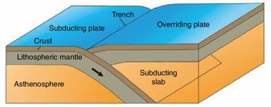
Figure 1 Movement of the tectonic plate (Earth’s outer shell: Crust & Lithospheric Mantle) generate in-situ stress (from Duarte & Schellart[1]).
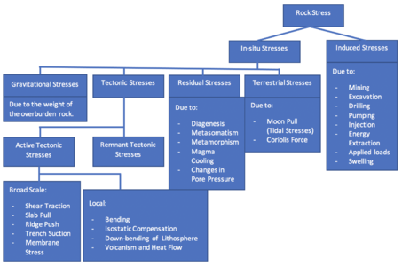
Figure 2 Summary of the different factors causing rock stress (from Amadei & Stephanson[2]).


Notation of Stress
Stress is often represented by the Greek letter sigma (σ) and can be defined as the force applied over an area. When the force acts perpendicular to a plane, the stress is called a Normal Stress (σn), whereas when the force acts parallel to a plane, the stress is called a Horizontal Stress (σs). Generally, the stress acting on a plane is oblique which means it is neither parallel nor at a right angle to that plane. Therefore, the stress vector is resolved into normal and shear components that are aligned with the three cartesian axes: x, y and z. Since the shear stress component is generally not aligned with these axes, it needs to be resolved further into two components (Figure 3).
These components act on each visible face of an infinitesimal cube used to represent a point within a rock mass. This results in a total of nine stress components that can be organized in a 3x3 matrix, called the stress tensor (Figure 4). Assuming the rock is at rest, the stresses of equal magnitudes and opposite directions will cancel out each other and prevent the cube from rotating. There is a special orientation in space where all shear stresses equal to zero and only three normal compressive components exist, called principle stresses (Figure 5). The three principle stresses are the vertical stress (σV), the maximum horizontal stress (σH), and the minimum horizontal stress (σh).
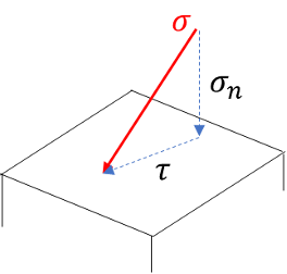
Figure 3 Illustration of resolving an oblique stress vector into normal and shear components.
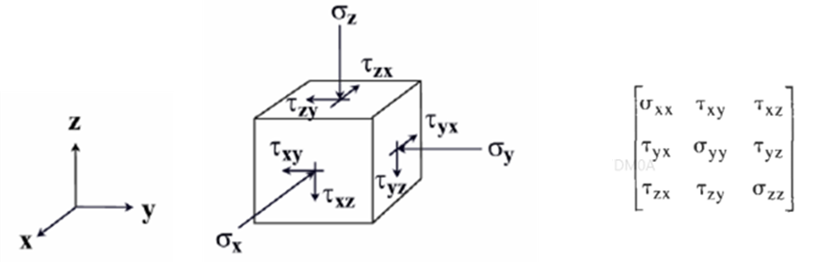
Figure 4 Stress tensor components of an infinitesimal cube, representing a point in the rock, and their alignment with the cartesian axes (from Zhang[3]).

Figure 5 Special orientation in space where all shear stresses equal to zero (from Zhang[3]).


Mohr Circle and Diagram
Mohr circle is a graphical way of representing the state of stress in a solid body. It is used to graphically construct the normal and shear stresses acting on a plane of arbitrary orientation (θ) through a point in the formation. All possible combinations of shear and normal stresses fall inside the Mohr circle and it can be used in two or three dimensions.
2-D Mohar Circle
The horizontal and the vertical axes represent the normal and the shear stress respectively (Figure 6). The difference between the maximum principle stress (σ1) and the minimum principle stress (σ3) is called the differential stress and it represents the radius of the Mohr circle. The center of Mohr circle for any given two principal stresses is calculated as follows:

The maximum shear stress is given by the circle’s radius R:


3-D Mohr Circle
Mohar diagram can also represent the state of stress in three dimensions. The state of stress is presented as three circles which connect the three principle stresses in one Mohar diagram (Figure 7). The three principle stresses are plotted in the horizontal axis. The center of each circle is calculated as follow:


The radius of each circle is calculated as follow:


In-situ Stress Estimation
Vertical Component
The vertical stress (σv) acting on a horizontal plane can be estimated using the weight of the overlaying layers, as shown below:
- (measured in Mega Pascal)
- where σ is the unit weight of the overlaying rock [mN/ m3].
- z is the depth to point below surface [m].
- Pa is the atmospheric pressure (usually neglected = 0).

In case the vertical stress is caused by multiple layers of different rock types, it can be estimated using the following formula:
- where a, b, and c represent different layers.

Horizontal Component
The horizontal stress due to the tectonic movements, can be estimated using the ratio of the average horizontal stress to the vertical stress, as shown below:

where
- γ is the unit weight of the overlaying rock [mN/ m3].
- z is the depth to point below surface [m].
- k is the ratio of the average horizontal stress to the vertical stress.
The ratio (k) can be determined using the simplified equation provided by Sheorey[5]:

where Eh is the average deformation modulus measured in a horizontal direction.
Determination Methods of Stress
Determination methods of in-situ stresses can be classified into three categories as shown in Figure 8. The loading method involves disturbing the in-situ stress condition in the rock such as pumping high pressure fluid into the formation to create fractures. The relief method involves isolating the rock sample partially or completely from the surrounding rocks and observe the natural rock response to the in-situ stress. Other methods can be used to deduce the in-situ stress in the rock such as geological and geophysical method. Since stress cannot be measured directly, the methods rely on the measurements of any change in rock volume or shape (Strain). Figure 9 shows the integration of the different methods in one workflow to infer the in-situ stress state.
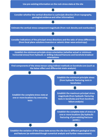
Figure 9 Workflow of the integrated approach for in-situ stress determination (from Hudson et al, 2003, as cited in Zhang[3]).


In-situ Stress from Historical Data
Databases of topographical and tectonic information can be used to determine the principal stress directions. The World Stress Map is an online database that compiles in-situ stress measurements and present the maximum horizontal stresses on the world map (Figure 10).

In-situ Stress from Field Investigations
The following subsections showcase the different methods of in-situ stress determination:
Conventional Hydraulic Fracturing (Fracking)
Hydraulic fracturing can be used to measure the maximum and minimum horizontal stresses at great depths below the surface. This method involves pumping fluid into an isolated target formation, until the fracture breakdown pressure is reached and the fracture is created. The fracture will propagate perpendicular to the minimum horizontal stress as shown in Figure 11. Then, the well is shut-in (pumping stops), causing the pressure to subside until it reaches the fracture closure pressure and the fractures will start to close. The pumping of fluid starts again until the fracture reopening pressure is reached and the previously closed fractures reopen. Multiple pumping cycles (minimum of three) are required to measure the reopening pressure. After the last pumping cycle, the shut-in pressure (Ps) is recorded and is considered equal to the minimum horizontal stress (σh). Then the maximum horizontal stress (σH) can be calculated as follows:
- Where Ps is the shut-in pressure.
- Po is the pore pressure, which is the pressure of fluid inside the rock.
- Pr is the reopening pressure.


Hydraulic Testing of Pre-existing Fracture (HTPF)
Hydraulic Testing of Pre-existing Fracture is similar to the conventional fracking. However, no fractures are created by the HTPF method. It is used to reopen a pre-existing fracture in the formation (Figure 12). HTPF method requires the knowledge of the exact orientation and location of the pre-existing fractures before pumping fluid into the formation. HTPF can determine the normal stress acting perpendicular to the pre-existing fractures, which is equal to the shut-in pressure.

Formation Integrity (FIT) Test or Leak-off Test (LOT)
FIT and LOT are used interchangeably by petroleum engineers because they follow similar procedures, however, the purpose of each is different. During FIT, the surface pressure increases until it reaches the required pressure to test the strength of the formation, without the intention of breaking the rock. The Leak-off test is used to determine the strength and the fracture pressure of the formation as well as the minimum horizontal stress. This procedure is similar to fracking by pumping fluids, however, instead of measuring the shut-in pressure, the leak-off pressure (Plo) is measured. The leak-off pressure is defined as the pressure at which the fluid will leak into the formation and it is equal to the minimum horizontal stress.
Extended Leak-off Test (XLOT)
The extended leak-off test (XLOT) is an extension of LOT and it is similar to fracking which involves propagating of a fracture by pumping fluids. However, XLOT does not determine the stresses orientation. Figure 13 shows the recorded pressure during XLOT. The horizontal stresses values can be estimated as follow:


Where Plo is the leak-off pressure.

Overcoring Method
Overcoring method is used to determine in-situ stresses from a rock sample extracted from shallow depths, and released to expand freely. This method involves a sequence of steps illustrated in Figure 14. The process of cutting the hollow cylindrical rock, using the tool shown in figure 15, is called overcoring and the resulting change in shape is measured using a device called stressmeter. In general, the maximum expansion of the rock sample occurs in the direction of the maximum horizontal stress (σH).
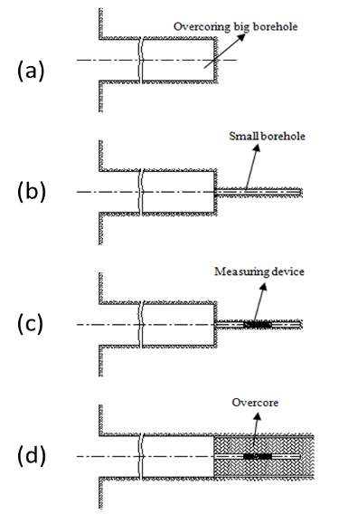
Figure 14 The sequence of overcoring method: (a) Drilling a large diameter hole. (b) Drilling a smaller pilot hole. (c) Placing the measuring device in the smaller hole. (d) Drilling the large diameter hole is resumed and the measuring device is overcored. (from Guo et al.[11]).
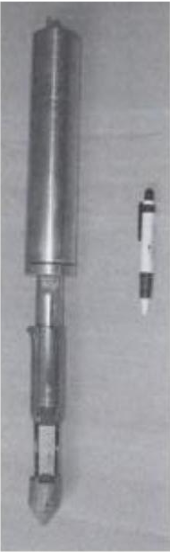
Figure 15 Overcoring tool (from Hudson[12]).


Borehole Slotting
Borehole slotting method involves cutting different 25-mm deep slots at the wall of a wellbore using a diamond saw. The cut slots form a half circle as shown in Figure 16. The strain changes before, during, and after cutting the slots, are measured using a sensor and converted into stress readings. This method helps avoid the high cost of using other in-situ measurement methods.

Lab Based Core Sample Testing
Cores are cylindrical rock samples that are collected during or after well drilling. They are sent to the laboratory for further testing. The Anelastic Strain Recovery (ASR) is a method used to determine the in-situ stresses and their orientation from cores by measuring the strain over time.
The core is placed in a container filled with silicon and the strain is monitored (Figure 17). The change in the core dimension is related to the microcracks creation in the rock when in-situ stress is relieved. The alignment of these micro fractures depends on the direction of the principal stresses. When the stress is relieved, the core tends to expand most in the maximum stress relief direction, and least in the minimum stress relief direction. The volume of the microcracks is proportional to the values of the in-situ stresses.

Geological Method (Geologic Structure)
Geologic structures at the surface, that were created by tectonic processes, can give a reliable indication of the principle stress orientations. Geological structures such as the volcanic vent alignment and active vertical fractures are formed perpendicular to the minimum horizontal stress and parallel to the maximum horizontal stress (Figure 18a, b).
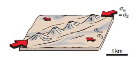
Figure 18a Volcanic vent alignment (from Fossen[4]).
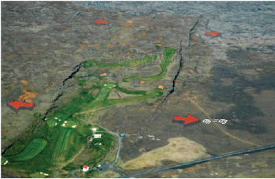
Figure 18b Active vertical fracture (from Fossen[4]).


Geophysical Method (Borehole Breakouts)
Borehole breakout is the breaking zone of the wellbore’s wall, causing the hole to have an irregular elongated shape, from which the orientation of the horizontal stresses can be inferred. The breaking of fragments is assumed to occur parallel to the minimum horizontal stress and perpendicular to the maximum horizontal stress (Figure 19).

The shape of the hole is identified using four-arm caliper tools or well imaging tools (Figure 20). These tools are used during the drilling of the well for petroleum exploration and production. The four caliper arms push against the wall as they move along the wellbore, recording the shape of the hole, from which the orientation of the horizontal stresses can be inferred.

Applications of In-situ Stress
Petroleum Engineering
Estimation of in-situ stresses have many petroleum engineering applications, i.e., optimizing well placement and well completion, stimulation job design, sanding analysis, etc. The following sections showcase examples of different in-situ stress applications in the field.
Wellbore Stability Analysis (Optimizing Well Placement)
In fields operated by ONGC in India, the horizontal stress orientations were determined using logging tools to help optimize the trajectory of future wells in any fault system[15]. Figure 21 summarizes the different fault systems in which wells can be drilled. In a normally faulted system, the preferred drilling direction for inclined or horizontal wells is the minimum horizontal stress direction. The resulting wellbore tends to be more stable, thus requires lower mud weight and lower cost. Whereas, in a strike-slip or thrust fault system, the preferred drilling direction for inclined or horizontal wells is the direction of the maximum horizontal stress.

Sanding Analysis (Optimizing Well Completion)
The determination of horizontal stress orientations is also important for sand avoidance in oriented perforations. In unconsolidated sand reservoirs, it is preferred to perforate in the direction of the maximum horizontal stress because sanding starts in the direction of minimum horizontal stress. This helps postpone any sand-related issues for some time.
Stimulation Job Design
The determination of horizontal stress orientations is also important for optimizing well stimulation jobs. The preferred direction for stimulation jobs is the direction of the maximum horizontal stress because all the induced fractures eventually tend to align themselves in this direction.
Mining Engineering

Wellbore Stability Analysis (Safety of Mining Operations)
In-situ stress measurements taken from different mining and civil engineering projects in South Africa, were compiled in a database to provide a useful source for realistic design and layout analysis of new mining areas[16]. Figure 17 shows the orientations of the horizontal stresses in South Africa. Optimizing the in-situ stress distribution and concentration in the rock by optimizing the wellbore stability is important for the safety of mining operations.
Geology/Geophysics (Earthquake Prediction)
In-situ stresses were measured using different methods in several boreholes located in Japan and they were generally consistent with the plate tectonic model despite topographical disturbances.[17] Results showed that even the shallow stress measurements reflect to some extent the tectonic stresses and monitoring stress changes can detect the build-up of tectonic stress which may cause earthquake. Also, stress measurements help detect areas with abnormal state of stress and provides a better understanding of the tectonic processes responsible for earthquakes.
Sources
- Ameen, M., 2003, Fracture and in-situ stress characterization of hydrocarbon reservoirs: Definitions and introduction, in M. Ameen, ed., Fracture and in-situ stress characterization of hydrocarbon reservoirs: Geological Society (London) Special Publication 209, p. 1-6.
- Bock, H., and P. Hartkorn, 1991, Recent developments and experience with the borehole slatter stressmeter: 7th ISRM Congress, Aachen, Germany.
- Butterworth, S. R., P. N. Chroston, C. A. Davenport, N. R. Brereton, and C. J. Evans, 1991, Anelastic strain recovery of rock core from the English midlands, in Proceedings of the 32nd U.S. Symposium on Rock Mechanics, Norman, Oklahoma, July 10-12, 1991.
- Daneshy, A. A., 2004, On the accuracy of in-situ stress measurements by hydraulic fracturing, in Proceedings of the Gulf Rocks 2004, the 6th North America Rock Mechanics Symposium (NARMS), Houston, Texas, June 5-9, 2004.
- Gray, I., and L. See., 2007, The measurement and interpretation of In-situ stress using an overcoring technique from surface, in Proceedings of the 1st Canada-U.S. Rock Mechanics Symposium, Vancouver, Canada, May 27-31, 2007.
- Harrison, J. P., and J. A. Hudson, 2000, Engineering rock mechanics – Part 2: Illustrative worked examples: Oxford, U.K., Elsevier Science, 524 p.
- Herget, G., 1988, Stresses in rock: Rotterdam, Balkema, 177 p.
- Hoek, E., and E. T. Brown, 1980, Underground excavations in rock: London, Institution of Mining and Metallurgy, 527 p.
- Hudson, J., and J. Harrison, 1997, Engineering rock mechanics: An introduction to the principles: Amsterdam, Netherlands, Elsevier, 456 p.
- Karakas, A., 2008, Practical rock engineering: Environmental and Engineering Geoscience, vol. 14, no. 1, p. 55-57, doi:10.2113/gseegeosci.14.1.55
- Koolen, A. J., and H. Kuipers, 1983, Agricultural soil mechanics: Springer Advanced Series in Agricultural Sciences 13, 241 p.
- Kunze, K. R., and R. P. Steiger, 1991, Extended leakoff tests to measure in situ stress during drilling, in Proceedings of the 32nd U.S. Symposium on Rock Mechanics, Norman, Oklahoma, July 10-12, 1991.
- Li, G., A. Lorwongngam, and J.-C. Rogiers, 2009, Critical review of leak-off test as a practice for determination of in-situ stresses, in Proceedings of the 43rd U.S. Rock Mechanics Symposium and 4th US-Canada Rock Mechanics Symposium, Asheville, North Carolina, June 28-July 1, 2009, p. 804-808.
- Marshak, S., 2015, Earth: Portrait of a planet (5th ed.): New York City, W. W. Norton & Company, 984 p.
- Pei, Q., X. Ding, B. Lu, Y. Zhang, S. Huang, and Z. Dong, 2016, An improved method for estimating in situ stress in an elastic rock mass and its engineering application: Open Geosciences, vol. 8, no. 1., p. 523-526, doi:10.1515/geo-2016-0047.
- Teraghi, K., and F. E. Richart, 1952, Stresses in rock about cavities: Geotechnique, vol. 3, no. 2, p. 57–90.
- Zhang, J., 2019, Applied petroleum geomechanics: Amsterdam, Netherlands, Elsevier, 534 p.
- Zhang, Y., S. Yin, and J. Zhang, 2021, In situ stress prediction in subsurface rocks: An overview and a new method: Geofluids, vol. 2021, 11 p.
References
- ↑ Duarte, J., C., and W. P. Schellart, 2016, Introduction to plate boundaries and natural hazards, in J. C. Duarte and W. P. Schellart, eds., Plate boundaries and natural hazards: AGU Geophysical Monograph Series 219, p. 1-10.
- ↑ 2.0 2.1 Amadei, B., and O. Stephansson, 1997, Rock stress and its measurement: Amsterdam, Netherlands, Springer Dordrecht, 490 p.
- ↑ 3.0 3.1 3.2 3.3 3.4 Zhang, L., 2016, Engineering properties of rocks: Amsterdam, Netherlands, Elsevier, 394 p.
- ↑ 4.0 4.1 4.2 4.3 4.4 Fossen, H., 2016, Structural geology: Cambridge, U.K., Cambridge University Press, 524 p.
- ↑ Sheorey, P. R., 1994, A theory for in situ stresses in isotropic and transverseley isotropic rock: International Journal of Rock Mechanics and Mining Sciences & Geomechanics Abstracts, vol. 31, no. 1, p. 23-34
- ↑ 6.0 6.1 Heidbach, O., A. Barth, B. Müller, J. Reinecker, O. Stephansson, M. Tingay, and A. Zang, 2016, WSM quality ranking scheme, database description and analysis guidelines for stress indicator: World Stress Map Technical Report 16-01
- ↑ Morawietz, S., O. Heidbach, K. Reiter, M. Ziegler, M. Rajabi, G. Zimmerman, B. Müller, and M. Tingay, 2020, An open-access stress magnitude database for Germany and adjacent regions: Geothermal Energy, vol. 8, article 25.
- ↑ 7 Hoeksema, R., 2015, The defining series: Elements of hydraulic fracturing: Schlumberger.
- ↑ Lin, H., J. Oh, H. Masoumi, I. Canbulat, C. Zhang, and L. Dou, 2018, A review of in situ stress measurement techniques, in N. Aziz, and B. Kininmonth, eds: Proceedings of the 2018 Coal Operators' Conference, February 18-20, 2018, Wollongong, Australia.
- ↑ Kartevoll, M., 2009, Drilling problems in depleted reservoirs, Master's thesis, University of Stavanger, Stavanger, Norway, 33 p.
- ↑ Guo, Q., F. Ren, H. Guo, L. Zhao, and Z. Yan, 2013, Strain sensors with temperature compensation employed for in situ stress monitor: TELKOMNIKA Indonesian Journal of Electrical Engineering, vol. 11, no. 11, p. 6296-6303.
- ↑ Hudson, J., 2003, Strategy and tactics for rock stress estimation, in K. Sugawara, Y. Obara, and A. Sato, eds., Rock stress '03: Proceedings of the Second International Symposium on Rock Stress, Kumamoto, Japan, November 4-6, 2003, p. 3-21.
- ↑ Kanduth, H., R. Corthesy, and D. Gill, 1991, Validation of borehole slotting as a method for in situ stress measurements: Paper presented at the 7th ISRM Congress, Aachen, Germany, September 1991.
- ↑ Lin, W., E. Yeh, H. Ito, T. Hirono, W. Soh, C. Wang, K. Ma, J. Hung, and S. Song, 2007, Preliminary results of stress measurement using drill cores of TCDP hole-A: An application of anelastic strain recovery method to three-dimensional in-situ stress determination: Terrestrial, Atmospheric and Oceanic Sciences, v. 18, p. 379-393.
- ↑ Tiwari, R., 2013, Recognizing horizontal stress orientation for optimizing well placement and well completion jobs: SPG 10th Biennial International Conference and Exposition, Kochi, India, November 23-25, 2013, 5 p.
- ↑ 16.0 16.1 Stacey, T., and J. Wesseloo, 1998, In situ stresses in mining areas in South Africa: South African Institute of Mining and Metallurgy, vol. 98, p. 365-368.
- ↑ Koide, H., K. Hoshino, Y. Nishimatsu, and S. Koizumi, 1987, In situ stress measurements in the Kanto-Tokai region of Japan for the prediction of earthquake, in Proceedings of the 2nd International Symposium on Field Measurements in Geomechanics, Kobe, Japan, April 6–9, 1987, vol. 1, p. 125–134.