Wellbore trajectory
| Development Geology Reference Manual | |

| |
| Series | Methods in Exploration |
|---|---|
| Part | Wellsite methods |
| Chapter | Wellbore trajectory |
| Author | Curtis Cheatham |
| Link | Web page |
| Store | AAPG Store |
Wellbore trajectory is controlled by the type of bottom hole assembly used and the weight on the bit. The bottom hole assembly, or BHA, is that portion of the drill string closest to the drill bit. It consists of several components:
- Heavy-weight drill pipe, which has the same outer diameter as regular drill pipe but with thicker walls for greater weight, used as a transition between drill collars and drill pipe.
- Drill collars, which are heavy, large diameter pipe located above the bit and below the heavy wall and used to apply weight to the bit.
- Stabilizers, which are short drill collars with larger diameter blades that are used to control contact with the borehole wall.
- Subs, which are devices used to connect various parts of the BHA.
There are two basic types of wellbore trajectories:
- Vertical or straight
- Directional, including both deviated and horizontal wellbore trajectories
Vertical or straight wellbore[edit]

A vertical hole is called a “straight” hole. However, some minor deviation from vertical often occurs naturally. This is related to formation properties, such as dip angle and hardness, and to other factors, such as the BHA, the bit design, and the weight on the bit.
Two types of BHAs are commonly used to drill a vertical hole: slick and pendulum. A slick BHA consists of a drill bit, drill collars, heavy-weight drill pipe, and regular drill pipe. The name slick is related to the absence of stabilizers. Slick BHAs have limited application due to their high potential for becoming differentially stuck. Square or spiral collars can be used in conjunction with slick BHAs when differential sticking is known to occur. In addition, slick BHAs can be run when there is a risk of losing the BHA due to hole problems.
A pendulum BHA is probably the most often used assembly for drilling a vertical hole. A pendulum BHA is similar to a slick BHA, but contains one or more stabilizers (Figure 1). The closest stabilizer to the bit acts as a pendulum point. Gravity tends to force the bit to the “low side” of the hole, decreasing hole angle. Pendulum BHAs are run at a high RPM rate and a low weight-on-bit (WOB) rate in areas where deviation needs to be minimized.
Directional wellbore[edit]
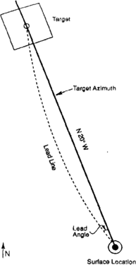
Figure 2 Right-hand walk and lead angle.
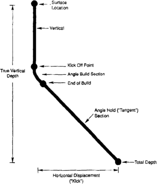
Figure 3 Directional well design example: build and hold.
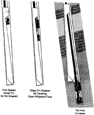
Figure 4 Using an open hole whipstock for sidetracking
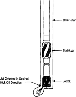
Figure 5 Kicking off with a jet bit.]]
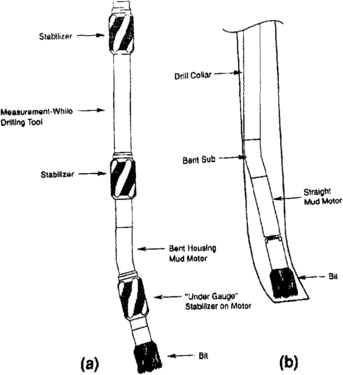
Figure 6 (a) Steerable bottom hole assembly, (b) Kicking off with a bent sub and straight mud motor.]]
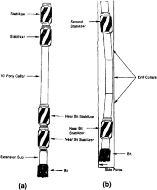
Figure 7 (a) Packed bottom hole assembly, (b) Fulcrum effect for build angle.]]


Directional drilling refers to any method employed to hit a predetermined subsurface target. One application of directional drilling is the development of offshore fields. Field development costs are reduced by directionally drilling many wells from one (or more) platforms. Other applications for directional drilling include the following:
- Building a surface location away from the bottom hole location to avoid cultural or topographic restrictions
- Sidetracking around a “fish” or lost open hole
- Sidetracking out of casing for recompletions or collapsed casing
- Drilling a relief well to kill a blowout
- Increasing contact between the reservoir and the wellbore, (e.g., horizontal drilling)
To hit a subsurface target, control must be exercised on both the angle of hole inclination from vertical (the drift or angle) and the azimuth angle (the direction). Wellbores have a tendency to move from left to right as the hole is drilled. This phenomenon, known as “walking to the right,” is presumably due to right-hand rotation of the bit and drill string and is affected by inclination angle, rotary speed, weight on the bit, formation dip and strike, and bit design. Most directional wells are oriented to the left of the direction of the target azimuth by an amount known as the lead angle (Figure 2). By compensating for right-hand walk in this fashion, the wellbore is allowed to move naturally to the right, forming an arc into the target.
“Kicking off” a directional well[edit]
In directional wells, the wellbore will be deviated at a preselected depth known as the kick-off point. An example of a directional well plan called “build and hold” is shown in Figure 3. A borehole inclination of at least 15° is desirable since it is harder to maintain directional control in holes with shallower deviation angles (Adams, 1985[citation needed]). However, wells with higher deviation angles can present operational problems (such as running wireline logs to total depth).
Whipstock method[edit]
The oldest method of kicking off or deviating a wellbore uses an open hole whipstock (Figure 4), which is a casing joint with an upward-tapering wedge cut out of one side. Although this operation is time consuming, it is still occasionally used to sidetrack around fish or abandoned open holes. Whipstocks are also used to sidetrack out of casing by milling a “window” and deflecting the wellbore using a mud motor.
Jet bit[edit]
Another kicking-off method uses a jet bit. The bit has one large nozzle that erodes a pocket from the hole bottom in the desired trajectory (Figure 5). Weight is applied to the bit while it is rotated into the pocket. This procedure is repeated until the desired trajectory is achieved. The disadvantage of jetting is that it is highly dependent on formation hardness. Some formations are too hard to be hydraulically eroded, and some soft formations erode too quickly, making it difficult to jet in the desired trajectory.
Bottom hole assemblages used to kick off wells[edit]
Two types of BHAs are used to kick off wells:
- Rotary BHAs, in which the power to turn the bit is supplied by the rotary table
- BHAs that use a downhole motor to provide bit power
There are two different downhole power sources: mud turbines and positive displacement mud motors. Both systems use the hydraulic energy of the mud to rotate the bit. Mud motors combined with a bend in the BHA are used to drill the well directionally. The bend is located in the motor housing (bent housing motor) (Figure 6a) or in a short sub (bent sub) directly behind the motor (Figure 6b). The purpose of the bend is to tilt the bit axis relative to the hole axis.
To change course, drilling stops, the bend in the BHA is oriented to the new borehole trajectory and the bit drills ahead. This procedure is called sliding because the entire BHA above the motor is moving downhole without rotating. This system originally had several limitations:
- Short bit life
- Low power motors with low reliability
- No means to monitor the progress of the wellbore trajectory continually
Current technology has simplified directional drilling based on improvements in the following:
- Polycrystalline diamond compact (PDC) bits.
- Improved motor design.
- Reliable measurement while drilling (MWD) tools and systems. This system allows the directional driller to monitor the azimuth and inclination of the borehole continously near the bit and make changes as required (see Measurement while drilling).
- Downhole adjustable bent subs, called steerable subs.
Steerable subs can be reset by changing the pump pressure. This changes the angle of the bent sub from straight to +1°. The main advantage of steerable systems is that, after achieving the desired wellbore deflection, it is possible to continue drilling without tripping. If needed, changes in wellbore trajectory can be made at any time in very gradual steps, which reduces the probability of severe dog legs. The main disadvantage of steerable systems is that they are more expensive than other deflection systems.
Drilling a directional well[edit]
After the well has been kicked off, drilling proceeds either by maintaining the wellbore trajectory or by altering it as required to hit the target(s). Three types of rotary BHAs can be used in a directional well to drill ahead or to hold, drop, or build the inclination angle:
- Drill ahead—After the well has been kicked off, the entire drill string is rotated to drill ahead while maintaining the trajectory. An undergauge stabilizer is often included on the motor to reduce the tendency to drop the angle. Further corrections in trajectory are made by orienting and sliding.
- Hold angle—These require BHAs that are called packed because they contain many stabilizers. This tends to limit changes in wellbore trajectory (Figure 7a).
- Drop angle—The pendulum BHA, discussed earlier, is also used for dropping the angle (see Figure 1).
- Build angle—This requires a near bit stabilizer to act as a fulcrum point. The bend in the drill collars above the near bit stabilizer causes the bit axis to tilt relative to the hole axis (Figure 7b).
Horizontal wellbore[edit]

A horizontal well is a special type of directional well. At a predetermined depth, the well is kicked off and, the angle is built to a 90 ° inclination. The major reasons for horizontal drilling are
- Intersecting many vertical fractures in a single wellbore
- Increasing production rate in low permeability formations
- Reducing water and gas coning problems
- Increased ultimate recovery
- Faster payout
Problems with horizontal wells include additional well costs and difficulties with formation evaluation, completion, and workover services.
Horizontal wells are classified as long, medium, or short radius, depending on the build rate from vertical to horizontal (Figure 8). As the build rate increases, the radius of curvature of the wellbore trajectory decreases. Long radius wells have smaller build rates and therefore reach a 90° inclination over a longer horizontal distance than short radius wells.
Long radius[edit]
Long radius design methods are used primarily for achieving extended reach from platforms and in applications where large horizontal displacement is desired. These wells are really just conventional directional wells with final hole inclinations of 90°. Build rates typically range from 2° to 6° per length::100 ft. More than depth::4000 ft of horizontal section can be drilled after reaching a 90 ° inclination.
BHAs used to provide wellbore trajectories for this type of well are similar to those used for conventional directional drilling. Steerable systems with bent housing motors are generally used for both the build and the horizontal sections. Slick BHAs with downhole motors are sometimes used to drill the horizontal portion of the well.
Medium radius[edit]
Medium radius horizontal wells use similar methods and equipment developed for long radius wells, although sometimes in a slightly different fashion. Build rates range from 8° to 20° per length::100 ft, and the maximum horizontal section drilled is presently greater than 4200 ft.[1] When build rates of greater than approximately 15° per length::100 ft are needed, BHAs with a double bend are used. A typical double bend BHA consists of a bent housing motor and a bent sub above the motor. Generally, this configuration is used only in a sliding mode since rotation can cause premature downhole failures due to the large cyclic bending stresses in the BHA.
Short radius[edit]
Short radius horizontal wells require different equipment than long or medium radius wells. Articulated (“wiggly”) drill collars, a whipstock with retrievable packer assembly, and other special equipment are used. Build rates of 1° to 3° per ft are needed to change from vertical to horizontal within a 30- to 90-ft window. Typical horizontal sections extend 200 to length::400 ft, with a record reach of more than depth::1200 ft. In special situations, pliable BHAs are used. These BHAs limit the reach of short radius wells but allow multiple drain holes to be drilled from the same vertical hole.
See also[edit]
- Drilling problems
- Mudlogging: drill cuttings analysis
- Introduction to wellsite methods
- Conventional coring
- Drilling fluid
- Land rigs
- Rig personnel
- Wellsite math
- Core handling
- Mudlogging: equipment, services, and personnel
- Core alteration and preservation
- Wellsite safety
- Sidewall coring
- Show evaluation
- Rate of penetration
- Mudlogging: the mudlog
- Well planning
- Pressure detection
- Drill stem testing
- Measurement while drilling
- Offshore rigs
- Fishing
- Core orientation
- Mudlogging: gas extraction and monitoring
- Well types
References[edit]
- ↑ Franco, A., 1990, “Hot play” gets hotter in the Austin Chalk: Drilling Contractor, June/July, p. 55.
External links[edit]
| find literature about Wellbore trajectory |