Fault seal quantitative prediction: shale smear factor, shale gouge ratio, and smear gouge ratio
Faults play an important role in creating hydrocarbon traps. For a better appreciation of the risks associated with fault-controlled prospects and of the production from faulted fields, it is important to understand the processes that contribute to fault seals. Given certain information about a fault cutting a reservoir sequence, it is desirable to predict the likely sealing behavior of each part of the fault system.
Shale smear factor
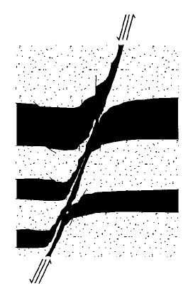
Figure 1 Field example of clay smears separating sandstones from Frechen lignite mines, Germany (Modified from Weber et al.[1]). Note tapering of clay (black) away from the source bed and the compound nature of the clay smear in the fault zone. (No scale on original figure.)
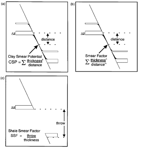
Figure 2 Figure 2-Smear factor algorithms for estimating likelihood of clay smear on a fault plane. (a) Clay smear potential (CSP)[2][3] given by the square of source-bed thickness divided by smear distance; (b) generalized smear factor, given by source-bed thickness divided by smear distance, with variable exponents; (c) shale smear factor (SSF)[4] given by fault throw divided by source-bed thickness. Methods (a) and (b) model the distance-tapering of shear-type smears, whereas method (c) models the form of abrasion smears.


Lindsay et al.[4] described outcrop studies of shale smears in a Carboniferous fluvio-deltaic sequence. In contrast to the sequence described by Weber et al.,[1] these rocks were lithified at the time of faulting (burial depth about 2 km). Lindsay et al.[4] recognized three types of shale smear: shear, abrasion, and injection.
- Shear smears are analogous to those described by Weber et al.[1](Figure 1). The thicknesses of the smears generally decrease with distance from the source bed, reaching a minimum in the region midway between the hanging-wall and footwall bed terminations.
- Abrasion smears, which are the commonest type in this lithified sequence, comprise a wafer-thin veneer that is abraded by a sandstone wall-rock as it slips past a shale bed. These smears tend to be thickest when derived from thicker source layers and when the fault throw is small. Larger throws tend to erode the shale veneer.
- Injection smears are a local response to volume changes during faulting. Injection smear thickness is not readily predictable.
Lindsay et al.[4] proposed a shale smear factor to constrain the likelihood of shale smear continuity. Based on their observations of abrasion smears in a lithified sequence, they define the shale smear factor (SSF) as (see Figure 2c)

The shale smear factor remains constant between the offset terminations because it does not depend on smear distance (although lateral variations in fault throw would have a corresponding effect on the calculated SSF). SSF thus models the profile of abrasion-type smears. From a study of 80 faults (excluding composite smears), Lindsay et al.[4] concluded that shale smears may become incomplete for an SSF greater than 7. Smaller values of SSF are more likely to correspond to continuous smears and therefore to a sealing layer on the fault surface. The values of SSF are not additive for compound smears because thin shales give higher SSF and dominate the sum. In such cases, a simple application of SSF values would take the minimum value (most sealing) from the relevant shale beds at that point on the fault.
Shale gouge ratio (SGR)

The shale gouge ratio is simply the percentage of shale or clay in the slipped interval. Figure 3a illustrates how this would be calculated, at a given point on a fault surface, for explicit shale beds (Equation 4):

The shale thicknesses are measured in a "window" with a height equal to the throw; therefore, this window represents the column of rock that has slid past this point on the fault. The definition can be extended for cases where the stratigraphic breakdown is by reservoir zone rather than by individual beds. In these cases, the net contribution of fine-grained material from each reservoir zone can be related to the clay content and thickness of the zone. The corresponding equation (Equation 5) is (see Figure 3b):
![{\displaystyle {\text{SGR}}={\frac {\Sigma [({\text{zone thickness}})\times ({\text{zone clay fraction}})]}{\text{fault throw}}}\times 100\%}](https://wikimedia.org/api/rest_v1/media/math/render/svg/c89fdfdf5d9b8ad1eb79b17b483b60d0549494c5)
Equation 5 reduces to equation 4 as the zonation approaches individual beds (assuming shale/clay beds are 100% clay material). The SGR represents, in a general way, the proportion of shale or clay that might be entrained in the fault zone by a variety of mechanisms. The more shaly the wall rocks, the greater the proportion of shale in the fault zone, and therefore the higher the capillary entry pressure. Although this is undoubtedly an oversimplification of the detailed processes occurring in the fault zone, it represents a tractable upscaling of the lithological diversity at the fault surface; the required information is simply fault displacement and shale fraction through the sequence.
The gouge ratio algorithm can be extended to include other lithologies in addition to shale/clay. For example, if numerous coal beds are present they may contribute to the fine-grained fault gouge, although less efficiently than smeared clay. In this case the coal units can be included in the summation and down-weighted with respect to the shale. Unfortunately both shale gouge ratio and smear gouge ratio are commonly called SGR. They are inversely related.
Smear gouge ratio (SGR)
Smear-gouge ratio is the ratio of sand to shale that has moved past some critical portion of the fault plane.[5] Although not simply relatable to the shale gouge ratio, the smear gouge ratio varies in an inverse manner; i.e., high shale gouge ratio corresponds to low smear gouge ratio and vice versa.
Further Reading
The information in this article is taken mainly from an AAPG Bulletin article:
- Yielding, G., B. Freeman, and D. T. Needham, 1997, Quantitative Fault Seal Prediction: AAPG Bulletin, vol. 81, no. 6, pp 897-917.
References
- ↑ 1.0 1.1 1.2 Weber, K. J., G. Mandl, W. F. Pilaar, F. Lehner, and R. G. Precious, 1978, The role of faults in hydrocarbon migration and trapping in Nigerian growth fault structures: Offshore Technology Conference 10, paper OTC 3356, p. 2643-2653.
- ↑ Bouvier, J. D., C. H. Kaars-Sijpesteijn, D. F. Kluesner, C. C. Onyejekwe, and R. C. Van der Pal, 1989, Three-dimensional seismic interpretation and fault sealing investigations, Nun River field, Nigeria: AAPG Bulletin, v. 73, p. 1397-1414.
- ↑ Fulljames, J. R., L. J. J. Zijerveld, R. C. M. W. Franssen, G. M. Ingram, and P. D. Richard, 1996, Fault seal processes, in Norwegian Petroleum Society, eds., Hydrocarbon seals-importance for exploration and production (conference abstracts): Oslo, Norwegian Petroleum Society, p. 5.
- ↑ 4.0 4.1 4.2 4.3 4.4 Lindsay, N. G., F. C. Murphy, J. J. Walsh, and J. Watterson, 1993, Outcrop studies of shale smear on fault surfaces: International Association of Sedimentologists Special Publication 15, p. 113-123.
- ↑ Skerlec, G. M., 1996, Risking fault seal in the Gulf Coast (abs.): AAPG Annual Convention Program and Abstracts, v. 5, p. A131.