Difference between revisions of "Shale gouge ratio"
Cwhitehurst (talk | contribs) |
Cwhitehurst (talk | contribs) |
||
| Line 12: | Line 12: | ||
Unfortunately both shale gouge ratio and smear gouge ratio are commonly called SGR. They are inversely related. | Unfortunately both shale gouge ratio and smear gouge ratio are commonly called SGR. They are inversely related. | ||
| − | == | + | ==Further reading== |
* Yielding, G, B. Freeman, and D. T. Needham, 1997, [http://archives.datapages.com/data/bulletns/1997/06jun/0897/0897.htm?q=%2BauthorStrip%3Ayielding Quantitative Fault Seal Prediction], AAPG Bulletin, vol 81, no. 6, 897-917 | * Yielding, G, B. Freeman, and D. T. Needham, 1997, [http://archives.datapages.com/data/bulletns/1997/06jun/0897/0897.htm?q=%2BauthorStrip%3Ayielding Quantitative Fault Seal Prediction], AAPG Bulletin, vol 81, no. 6, 897-917 | ||
Revision as of 16:49, 9 September 2014

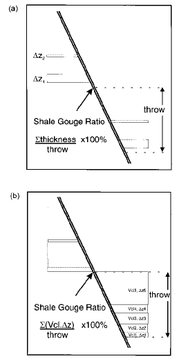
The shale gouge ratio is simply the percentage of shale or clay in the slipped interval. Figure 1a illustrates how this would be calculated, at a given point on a fault surface, for explicit shale beds: (4) SGR = (Σ (shale bed thickness) /fault throw))/fault throw ×100%
The shale thicknesses are measured in a "window" with a height equal to the throw; therefore, this window represents the column of rock that has slid past this point on the fault. The definition can be extended for cases where the stratigraphic breakdown is by reservoir zone rather than by individual beds. In these cases, the net contribution of fine-grained material from each reservoir zone can be related to the clay content and thickness of the zone. The corresponding equation is (see Figure 1b) (5)SGR = Σ (zone thickness) × (zone clay fraction)
Equation 5 reduces to equation 4 as the zonation approaches individual beds (assuming shale/clay beds are 100% clay material). The SGR represents, in a general way, the proportion of shale or clay that might be entrained in the fault zone by a variety of mechanisms. The more shaly the wall rocks, the greater the proportion of shale in the fault zone, and therefore the higher the capillary entry pressure. Although this is undoubtedly an oversimplification of the detailed processes occurring in the fault zone, it represents a tractable upscaling of the lithological diversity at the fault surface; the required information is simply fault displacement and shale fraction through the sequence. The gouge ratio algorithm can be extended to include other lithologies in addition to shale/clay. For example, if numerous coal beds are present they may contribute to the fine-grained fault gouge, although less efficiently than smeared clay. In this case the coal units can be included in the summation and down-weighted with respect to the shale.
Unfortunately both shale gouge ratio and smear gouge ratio are commonly called SGR. They are inversely related.
Further reading
- Yielding, G, B. Freeman, and D. T. Needham, 1997, Quantitative Fault Seal Prediction, AAPG Bulletin, vol 81, no. 6, 897-917