Difference between revisions of "Yowlumne field"
| Line 36: | Line 36: | ||
file:Mth14ch02f04.jpg|{{figure number|4}}Seismic line and cross section A-A' showing left-stepping geometries and cross-sectional lens shape of the Yowlumne fan. The line and section transect the fan from west to east, perpendicular to the direction of sediment transport. | file:Mth14ch02f04.jpg|{{figure number|4}}Seismic line and cross section A-A' showing left-stepping geometries and cross-sectional lens shape of the Yowlumne fan. The line and section transect the fan from west to east, perpendicular to the direction of sediment transport. | ||
file:Mth14ch02f05.jpg|{{figure number|5}} Map with cross sections X-Z and Y-Z showing basinward-stepping geometries exhibited by lobe-shaped sand bodies that make up the Yowlumne Sandstone. Note 660 m (2100 ft) of structural relief between oil-water contacts in the lobes of Units A and B. | file:Mth14ch02f05.jpg|{{figure number|5}} Map with cross sections X-Z and Y-Z showing basinward-stepping geometries exhibited by lobe-shaped sand bodies that make up the Yowlumne Sandstone. Note 660 m (2100 ft) of structural relief between oil-water contacts in the lobes of Units A and B. | ||
| + | file:Mth14ch02f06.jpg|{{figure number|6}} Maps showing fieldwide variations in the average reservoir pressure of the Yowlumne Sandstone. The variations indicate that Units A and B may represent separate compartments that are not in fluid communication with one another. | ||
</gallery> | </gallery> | ||
| Line 42: | Line 43: | ||
Well-log correlations and 3-D seismic data indicate downlap within the fan, with basinward progradation to the north and lateral progradation to the west ([[:file:Mth14ch02f04.jpg|Figure 4]], [[:file:Mth14ch02f05.jpg|Figure 5]]). In other words, lobe-shaped, shale-bounded reservoir layers in Unit B step to the left when facing basinward, in the direction of sediment transport (Jessup and Kamerling;<ref name=Jessupandkamerling_1991>Jessup, D. D., and M. Kamerling, 1991, [http://www.searchanddiscovery.com/abstracts/html/1991/pacific/abstracts/0368b.htm Depositional style of the Yowlumne sands, Yowlumne oil field, southern San Joaquin Basin, California] (abs.): AAPG Bulletin, v. 75, p. 368.</ref> Clark et al.<ref name=Clarketal_1996b>Clark, M. S., J. Melvin, and M. Kamerling, 1996, [http://www.searchanddiscovery.com/abstracts/html/1996/annual/abstracts/0027.htm Growth patterns of a Miocene turbidite complex in an active-margin basin, Yowlumne field, San Joaquin Basin, California] (abs.): AAPG Annual Convention Official Program, San Diego, 1996, v. 5, p. A27.</ref>). Thus, the basal productive layer (sand E) is thickest on the right (east) side of the fan, whereas the top layer (sand A) is thickest on the left (west). | Well-log correlations and 3-D seismic data indicate downlap within the fan, with basinward progradation to the north and lateral progradation to the west ([[:file:Mth14ch02f04.jpg|Figure 4]], [[:file:Mth14ch02f05.jpg|Figure 5]]). In other words, lobe-shaped, shale-bounded reservoir layers in Unit B step to the left when facing basinward, in the direction of sediment transport (Jessup and Kamerling;<ref name=Jessupandkamerling_1991>Jessup, D. D., and M. Kamerling, 1991, [http://www.searchanddiscovery.com/abstracts/html/1991/pacific/abstracts/0368b.htm Depositional style of the Yowlumne sands, Yowlumne oil field, southern San Joaquin Basin, California] (abs.): AAPG Bulletin, v. 75, p. 368.</ref> Clark et al.<ref name=Clarketal_1996b>Clark, M. S., J. Melvin, and M. Kamerling, 1996, [http://www.searchanddiscovery.com/abstracts/html/1996/annual/abstracts/0027.htm Growth patterns of a Miocene turbidite complex in an active-margin basin, Yowlumne field, San Joaquin Basin, California] (abs.): AAPG Annual Convention Official Program, San Diego, 1996, v. 5, p. A27.</ref>). Thus, the basal productive layer (sand E) is thickest on the right (east) side of the fan, whereas the top layer (sand A) is thickest on the left (west). | ||
| − | Variations in reservoir pressures and injection of radioactive tracers indicate weak compartmentalization of the reservoir, which results in separate permeability pathways along which fluids flow at different rates (Metz and Whitworth, their figure 9;<ref name=Metzandwhitworth_1984 | + | Variations in reservoir pressures and injection of radioactive tracers indicate weak compartmentalization of the reservoir, which results in separate permeability pathways along which fluids flow at different rates (Metz and Whitworth, their figure 9;<ref name=Metzandwhitworth_1984 /> Berg and Royo<ref name=Bergandroyo_1990>Berg, R. R., and G. R. Royo, 1990, Channel-fill turbidite reservoir, Yowlumne field, California, ''in'' J. H. Barwin, J. G. MacPherson, and J. R. Studlick, eds., Sandstone petroleum reservoirs: Casebooks in earth science: New York, Springer-Verlag, p. 467-487.</ref>). Most likely, these pathways represent different flow units that, for the most part, are in pressure communication over geologic time. Consequently, these compartments, which correlate to the shale-bounded, lobe-shaped reservoir layers already discussed, develop the same oil-water contact over thousands of years yet acquire slightly different pressures as the field is rapidly produced over tens of years. |
| + | |||
| + | <gallery mode=packed heights=300px widths=300px> | ||
| + | file:Mth14ch02f07.jpg|{{figure number|7}}Gross-sandstone isopach map of the Yowlumne sandstone showing separate depocenter thicks in Units A and B. The different depocenters indicate that the units may represent separate depositional accumulations, an interpretation consistent with Units A and B representing separate compartments with different oil-water contacts. | ||
| + | file:Mth14ch02f08.jpg|{{figure number|8}}Star plots of peak-height ratios from gas-liquid chromatograms of two representative oils in the field. These plots are consistent with plots of another six oils from the field that were also analyzed in the study, and they indicate that oils in Unit B are compositionally distinct from those in Unit A. Because variations at the D, K, M, N, and P axes are significant enough to indicate that oils in Units A and B are not in fluid communication with each other, Units A and B appear to represent separate reservoir compartments (Suhas Talukdar, Core Laboratories, Inc., written communication, 1998). | ||
| + | file:Mth14ch02f09.jpg|{{figure number|9}}Permeability profile from a 30-ft cored interval in the Yowlumne 91X-3 horizontal well revealing greater permeabilities in Bouma A layers relative to Bouma B and C layers, and slumped intervals. These variations result in the creation of reservoir permeability pathways that parallel bedding. | ||
| + | </gallery> | ||
| + | |||
| + | Several observations demonstrate that compartmentalization in the field also exists on larger scales. | ||
| + | * The reservoir in Yowlumne Unit A has, over time, consistently exhibited reservoir pressures that differ from those in the same interval in Unit B ([[:file:Mth14ch02f06.jpg|Figure 6]]). | ||
| + | * Gross sandstone isopach maps indicate separate northern (Unit B) and southern (Unit A) depocenters (loci of thickening), which appear to represent different depositional accumulations ([[:file:Mth14ch02f07.jpg|Figure 7]]). | ||
| + | * Because sandstones in Unit B have more quartz, less clay, and higher original porosity than the equivalent sandstones in Unit A, different depositional histories are indicated (Whelan<ref name=Whelan_1984>Whelan, H. T. M., 1984, Geostatistical estimation of the spatial distributions of porosity and percent clay in a Miocene Stevens turbidite reservoir: Yowlumne field, California: Master's thesis, Stanford University, Stanford, California, 126 p.</ref>). | ||
| + | * The oil-water contact in Unit B is 660 m (2180 ft) structurally lower than the contact in Unit A ([[:file:Mth14ch02f05.jpg|Figure 5]]). | ||
| + | * Although a few studies interpret a single oil-water contact steeply tilted to 5° (480ft/mi, 90.9 m/km), a large density difference of 0.154 g/cc between the oils (32° API) and formation waters (TDS [total dissolved solids] of 22,000 ppm) is more consistent with a lower-gradient oil-water contact. More likely, the large density contrast results in buoyant oils unlikely to support a contact tilted more than 1° (100 ft/mi, 18.9 m/km), even in the presence of a strong water drive. | ||
| + | * Comparisons of oil analyses from different parts of the field indicate that Units A and B are not in fluid communication ([[:file:Mth14ch02f08.jpg|Figure 8]]). | ||
| + | |||
Revision as of 21:30, 4 December 2015
| Horizontal Wells: Focus on the Reservoir | |
| |
| Series | Methods in Exploration No. 14 |
|---|---|
| Chapter | Characterization and exploitation of the distal margin of a fan-shaped turbidite reservoir: The ARCO-DOE 91X-3 horizontal well project, Yowlumne field, San Juaquin Basin, California |
| Author | Michael S. Clark, Rick K. Prather, John D. Melvin |
| Link | Web page |
| Store | AAPG Store |
Yowlumne is a giant oil field in the San Joaquin Basin, California (Figure 1), that has produced, through December 2000, more than 17.2 million m3 (108 million bbl) of oil and 2.7 billion m3 (94 billion ft3) of gas from upper Miocene, deep-water sandstones known as the Stevens (Figure 1).
These sandstones, which represent classic facies of organic-rich shales in the Monterey Formation (Figure 2), are some of the most prolific reservoirs in the basin and have contributed about 15% of more than 1.9 billion m3 (12.3 billion bbl) of oil produced in the area since 1864. Because Stevens oils derive from Monterey Shale source rocks, Yowlumne is part of a Monterey-Stevens petroleum system (Graham and Williams).[1]
Most production at Yowlumne is from the Yowlumne Sandstone, one of several discontinuous sandstone bodies collectively referred to as the Stevens (Figure 3).
Structure[edit]
The oil accumulation at Yowlumne is controlled in part by an anticlinal closure formed during Miocene-Pliocene deformation of the south basin margin. Yowlumne Unit A was created to waterflood the area of structural closure, but subsequent drilling established production in a stratigraphic accumulation on the north-dipping flank of the anticline also (Figure 1). Consequently, Yowlumne Unit B was created to flood the flank accumulation (Burzlaff,[2] Metz and Whitworth[3]). Thus, the field is a combination structural-stratigraphic trap.
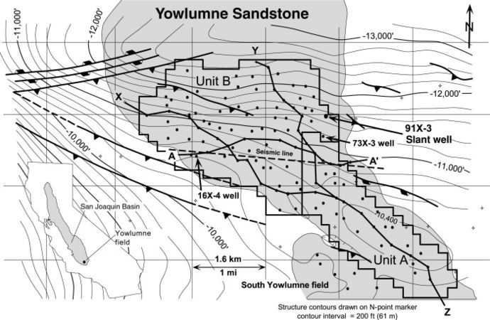
Figure 1 Structure map of Yowlumne field drawn on the N-point marker, a regional correlation horizon that marks the approximate top of the Stevens Sandstone. Note the fanlike shape of the Yowlumne Sandstone and the relationship of Yowlumne Units A and B to the anticlinal closure.
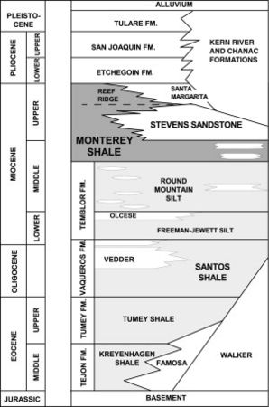
Figure 2 Stratigraphic section showing nomenclature for the Yowlumne field area. The Stevens is an informal unit that represents a deep-marine, clastic facies of the Monterey Formation, an organic-rich shale that is considered to be the main source rock for most of the oil produced from the basin.
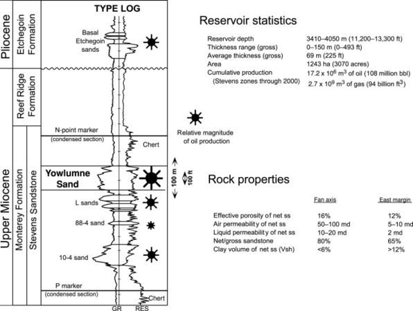
Figure 3 Type log for Yowlumne field with reservoir statistics and rock properties of the Yowlumne Sandstone. Reservoir quality decreases from the axis of the fan eastward toward the fan margin.


Flow units and reservoir compartments[edit]
More than 95% of production at Yowlumne field is from the Yowlumne Sandstone, a fan-shaped Stevens Sandstone body as much as 150 m (493 ft) thick (Figure 3). Bouma sequences evident in the cores from the field indicate deposition of this body by turbidity currents. Also, the Yowlumne Sandstune body is lens shaped in cross section and does not significantly incise underlying strata (Figure 4). Because large-scale channeling is absent, deposition was primarily as sheet sands transported by sediment-gravity flows.
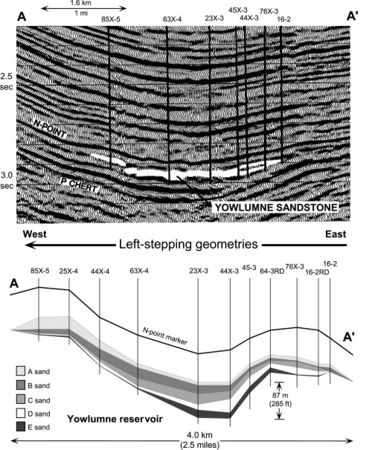
Figure 4 Seismic line and cross section A-A' showing left-stepping geometries and cross-sectional lens shape of the Yowlumne fan. The line and section transect the fan from west to east, perpendicular to the direction of sediment transport.
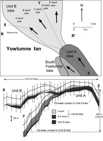
Figure 5 Map with cross sections X-Z and Y-Z showing basinward-stepping geometries exhibited by lobe-shaped sand bodies that make up the Yowlumne Sandstone. Note 660 m (2100 ft) of structural relief between oil-water contacts in the lobes of Units A and B.
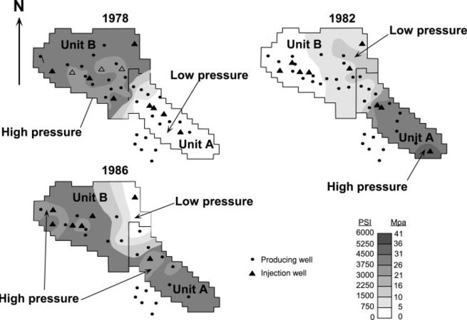
Figure 6 Maps showing fieldwide variations in the average reservoir pressure of the Yowlumne Sandstone. The variations indicate that Units A and B may represent separate compartments that are not in fluid communication with one another.


Thin shales divide the fan into lobe-shaped reservoir layers (Figure 4). Five of these—the A, B, C, D, and E sands—produce oil from Unit B. The W sand is a basal sixth layer that is wet and isolated by pressure from over-lying sandstones. Layers A through E merge into homogenous, clean sandstone on the west margin of the fan, yet contain interbedded shale on the east. For example, the 16x-4 horizontal well on the west side (Figure 1) penetrates a thick interval of clean sandstone (Marino and Schultz[4]). By contrast, the 73x-3 well on the east side (Figure 1) penetrates shale layers, some of which are two or more meters thick, interbedded with the reservoir sandstones.
Well-log correlations and 3-D seismic data indicate downlap within the fan, with basinward progradation to the north and lateral progradation to the west (Figure 4, Figure 5). In other words, lobe-shaped, shale-bounded reservoir layers in Unit B step to the left when facing basinward, in the direction of sediment transport (Jessup and Kamerling;[5] Clark et al.[6]). Thus, the basal productive layer (sand E) is thickest on the right (east) side of the fan, whereas the top layer (sand A) is thickest on the left (west).
Variations in reservoir pressures and injection of radioactive tracers indicate weak compartmentalization of the reservoir, which results in separate permeability pathways along which fluids flow at different rates (Metz and Whitworth, their figure 9;[3] Berg and Royo[7]). Most likely, these pathways represent different flow units that, for the most part, are in pressure communication over geologic time. Consequently, these compartments, which correlate to the shale-bounded, lobe-shaped reservoir layers already discussed, develop the same oil-water contact over thousands of years yet acquire slightly different pressures as the field is rapidly produced over tens of years.
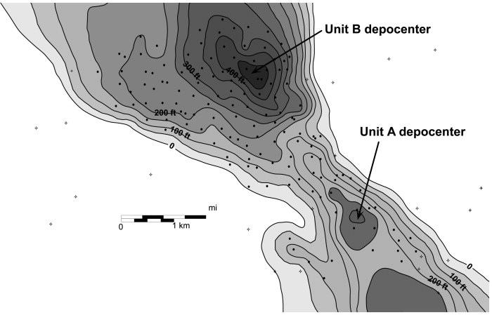
Figure 7 Gross-sandstone isopach map of the Yowlumne sandstone showing separate depocenter thicks in Units A and B. The different depocenters indicate that the units may represent separate depositional accumulations, an interpretation consistent with Units A and B representing separate compartments with different oil-water contacts.
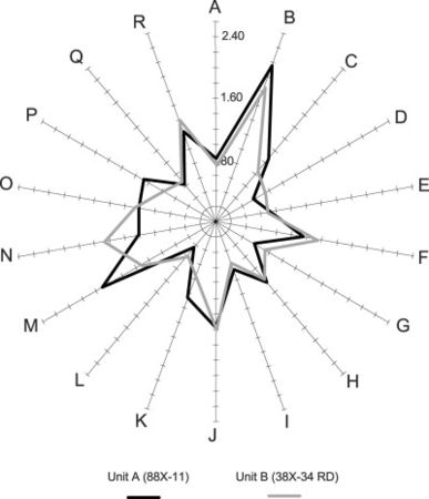
Figure 8 Star plots of peak-height ratios from gas-liquid chromatograms of two representative oils in the field. These plots are consistent with plots of another six oils from the field that were also analyzed in the study, and they indicate that oils in Unit B are compositionally distinct from those in Unit A. Because variations at the D, K, M, N, and P axes are significant enough to indicate that oils in Units A and B are not in fluid communication with each other, Units A and B appear to represent separate reservoir compartments (Suhas Talukdar, Core Laboratories, Inc., written communication, 1998).
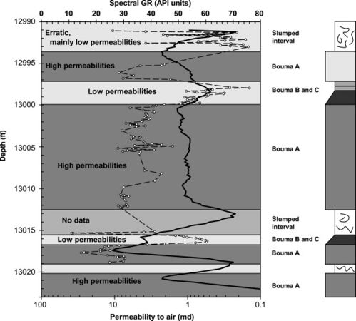
Figure 9 Permeability profile from a 30-ft cored interval in the Yowlumne 91X-3 horizontal well revealing greater permeabilities in Bouma A layers relative to Bouma B and C layers, and slumped intervals. These variations result in the creation of reservoir permeability pathways that parallel bedding.


Several observations demonstrate that compartmentalization in the field also exists on larger scales.
- The reservoir in Yowlumne Unit A has, over time, consistently exhibited reservoir pressures that differ from those in the same interval in Unit B (Figure 6).
- Gross sandstone isopach maps indicate separate northern (Unit B) and southern (Unit A) depocenters (loci of thickening), which appear to represent different depositional accumulations (Figure 7).
- Because sandstones in Unit B have more quartz, less clay, and higher original porosity than the equivalent sandstones in Unit A, different depositional histories are indicated (Whelan[8]).
- The oil-water contact in Unit B is 660 m (2180 ft) structurally lower than the contact in Unit A (Figure 5).
- Although a few studies interpret a single oil-water contact steeply tilted to 5° (480ft/mi, 90.9 m/km), a large density difference of 0.154 g/cc between the oils (32° API) and formation waters (TDS [total dissolved solids] of 22,000 ppm) is more consistent with a lower-gradient oil-water contact. More likely, the large density contrast results in buoyant oils unlikely to support a contact tilted more than 1° (100 ft/mi, 18.9 m/km), even in the presence of a strong water drive.
- Comparisons of oil analyses from different parts of the field indicate that Units A and B are not in fluid communication (Figure 8).
References[edit]
- ↑ Graham, S. A., and L. A. Williams, 1985, Tectonic, depositional, and diagenetic history of Monterey Formation (Miocene), central San Juaquin Basin, California: AAPG Bulletin, v. 69, p. 385-411.
- ↑ Burzlaff, A. A., 1983, Unitizing and waterflooding the California Yowlumne oil field: Society of Petroleum Engineers, SPE 11685, p. 187-194.
- ↑ 3.0 3.1 Metz, R. T., and J. L. Whitworth, 1984, Yowlumne oil field, in G. W. Kendall and S. C. Kiser, eds., Selected papers presented to San Joaquin Geological Society, v. 6, p. 3-23.
- ↑ Marino, A. W., and S. M. Schultz, 1992, Case study of Stevens sand horizontal well: Society of Petroleum Engineers, SPE 24910, p. 549-563.
- ↑ Jessup, D. D., and M. Kamerling, 1991, Depositional style of the Yowlumne sands, Yowlumne oil field, southern San Joaquin Basin, California (abs.): AAPG Bulletin, v. 75, p. 368.
- ↑ Clark, M. S., J. Melvin, and M. Kamerling, 1996, Growth patterns of a Miocene turbidite complex in an active-margin basin, Yowlumne field, San Joaquin Basin, California (abs.): AAPG Annual Convention Official Program, San Diego, 1996, v. 5, p. A27.
- ↑ Berg, R. R., and G. R. Royo, 1990, Channel-fill turbidite reservoir, Yowlumne field, California, in J. H. Barwin, J. G. MacPherson, and J. R. Studlick, eds., Sandstone petroleum reservoirs: Casebooks in earth science: New York, Springer-Verlag, p. 467-487.
- ↑ Whelan, H. T. M., 1984, Geostatistical estimation of the spatial distributions of porosity and percent clay in a Miocene Stevens turbidite reservoir: Yowlumne field, California: Master's thesis, Stanford University, Stanford, California, 126 p.
External links[edit]
| find literature about Yowlumne field |