Search results
Jump to navigation
Jump to search

File:AAPG Wiki banner.png Banner image, experiementing with annotated image to float text over(1,208 × 151 (286 KB)) - 18:42, 23 January 2014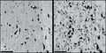
File:Figure-3.jpg ...nce, displaying organic matter (OM) bodies that are not evident in the SE1 image. From AAPG Memoir 102, Chapter 1, Huang et al., 2013, DOI: 10.1306/13391699(1,502 × 746 (180 KB)) - 17:32, 15 August 2014
File:Exploring-for-oil-and-gas-traps.png Book cover image.(432 × 558 (109 KB)) - 13:56, 17 January 2014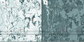
File:M102Ch1Fg4.jpg ...s much higher in BSE1; the topographical information is greater in the SE2 image (OM-associated nanopores are not visible in BSE1). From AAPG Memoir 102, Ch(1,492 × 746 (1.74 MB)) - 21:56, 14 August 2014
File:AlsaudKatterbauerFigure1.jpg Cross-well EM Image between three wells.(280 × 372 (30 KB)) - 22:11, 3 February 2022
File:MainPageDeltaicReservoirs.jpg Deltaic reservoirs MainPage Image(200 × 200 (19 KB)) - 18:59, 31 August 2015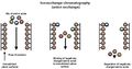
File:AlotaibiFigure6.jpg Image Source: https://sites.google.com/site/chromospectrum/i-exchange(936 × 488 (79 KB)) - 21:24, 3 February 2022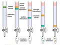
File:AlotaibiFigure7.jpg Column chromatography. Image Source: PrepGenie(900 × 678 (76 KB)) - 21:24, 3 February 2022
File:Development-geology-reference-manual.png Cover image for [[Development Geology Reference Manual]](480 × 524 (361 KB)) - 15:11, 14 August 2013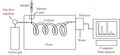
File:AlotaibiFigure2.jpg Gas chromatography system. Image Source: Bitesize Bio.(936 × 428 (53 KB)) - 21:15, 3 February 2022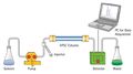
File:AlotaibiFigure8.jpg High-performance liquid chromatography (HPLC). Image Source: Toppr(914 × 510 (55 KB)) - 21:25, 3 February 2022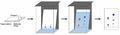
File:AlotaibiFigure9.jpg Thin-layer chromatography (TLC). Image Source: MZ-Analysentechnik GmbH(936 × 272 (32 KB)) - 21:25, 3 February 2022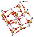
File:Titanium Substitutions in Zircon Unit Cell.jpeg Public Domain image sourced from cst-www.nrl.navy.mil, edited by Awebb6(351 × 382 (58 KB)) - 20:52, 29 November 2014
File:M102Ch1Fg6.jpg (a) A BSE and CL image of a polished shale sample. Orange-hued quartz grains reflect low-grade ...orphism (phyllite-schist). (b) Detail of a large quartz grain in center of image (arrow) displays multiple generations of growth in CL; this distinction in(502 × 518 (978 KB)) - 22:08, 14 August 2014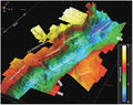
File:M115CH02FG02.jpg ...ng Graben at Base Cretaceous level, viewed from the southeast. Location of image shown in [[South Viking Graben|Figure 1]]. Lines 1–3 are the locations of(700 × 552 (112 KB)) - 20:30, 10 January 2019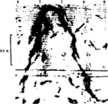
File:Borehole-imaging-devices fig3.png Borehole televiewer Image showing fracture (arrow) crossing the wellbore.(949 × 915 (25 KB)) - 18:53, 13 January 2014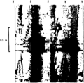
File:Borehole-imaging-devices fig5.png Borehole televiewer image showing breakouts (dark patches) at NNW and SSE.(951 × 935 (25 KB)) - 18:53, 13 January 2014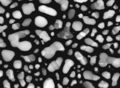
File:M102Ch1Fg5.jpg A BSE2 image of gold (Au) nanoparticles showing crystallographic contrast. From AAPG Mem(922 × 677 (123 KB)) - 22:04, 14 August 2014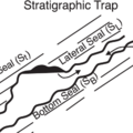
File:MainPageStratigraphicTraps.png Main Page image for the Stratigraphic trap seals article(400 × 400 (34 KB)) - 17:46, 5 January 2015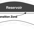
File:MainPageReservoirSystem.png Main Page image for the Reservoir system article.(200 × 200 (15 KB)) - 17:35, 5 January 2015


