Hydrostatic pressure-depth plot construction
| Exploring for Oil and Gas Traps | |

| |
| Series | Treatise in Petroleum Geology |
|---|---|
| Part | Critical elements of the petroleum system |
| Chapter | Formation fluid pressure and its application |
| Author | Edward A. Beaumont, Forrest Fiedler |
| Link | Web page |
| Store | AAPG Store |
A critical element in detecting the presence of hydrocarbons using formation fluid pressures is an accurate hydrostatic pressure gradient for zones of interest. We use the hydrostatic pressure gradient to determine the expected pressures for the zone of interest as if it had no hydrocarbons. Pressures exceeding hydrostatic pressures may be due to the presence of a hydrocarbon column. Most methods for determining hydrostatic pressures are not very precise. Other petrophysical data can help when the estimated hydrostatic pressure gradient is suspect.
The goal of constructing a hydrostatic pressure–depth plot is to identify pressures greater than the hydrostatic gradient that may correspond to a hydrocarbon-bearing zone. A hydrostatic pressure–depth plot can be constructed from any of the following:
- Measured pressures
- Regional rule-of-thumb pressure gradients
- Pressures calculated from water density
Calculated pressures are much less accurate than measured pressures but can be used with some effectiveness when they are supplemented with other petrophysical data.
Procedure: constructing a plot
The table below outlines a procedure for constructing a hydrostatic pressure-depth plot for a single well.
- Using graph paper with a linear grid, label the X-axis as pressure and the Y-axis as depth. Use as large a scale as possible. Also, make the Y-axis on at least one plot the same scale as on the well logs to aid in interpretation.
- Plot measured pressure from the aquifers (100% water saturation [Sw] ) in the well. If none is available, go to step 3.
- Plot measured pressure from the aquifers in nearby wells. If none is available, go to step 4.
- Calculate and plot hydrostatic pressures for a depth above and a depth below the zone of interest. Use the rule-of-thumb pressure gradient for that zone. If it is not available, calculate the gradient from the water density using density measured from the formation water or calculated from the water resistivity (Rw) . For help, see the following sections.
Calculating pressure gradients from water density
The formation fluid pressure at any depth in a well is a function of the average formation water density (ave. ρw) above that depth, not the density of the formation water at any particular depth. Formation water generally becomes more dense with increasing depth.
To calculate water pressure gradient (Pgrad), use the following formula:
where:
- ρw = water density
For example, given ave. ρ = 1.13, the equation works as follows:
Table of water pressure gradients
The table below lists hydrostatic pressure gradients, water density, and salinity in weight percent total dissolved solids (TDS).
| Gradient (psi/ft) | Density (g/cc) | TDS (ppm) | TDS (wt %) |
|---|---|---|---|
| 04.33 | 1.000 | 0 | |
| 0.437 | 1.010 | 13,500 | 13.5 |
| 0.441 | 1.020 | 27,500 | 27.5 |
| 0.444 | 1.029 | 37,000 | 37.0 |
| 0.445 | 1.030 | 41,400 | 41.4 |
| 0.451 | 1.040 | 55,400 | 55.4 |
| 0.454 | 1.050 | 69,400 | 69.4 |
| 0.459 | 1.060 | 83,700 | 83.7 |
| 0.463 | 1.070 | 98,400 | 98.4 |
| 0.465 | 1.075 | 100,000 | 100.0 |
| 0.467 | 1.080 | 113,200 | 113.2 |
| 0.471 | 1.090 | 128,300 | 128.3 |
| 0.476 | 1.100 | 143,500 | 143.5 |
| 0.480 | 1.110 | 159,500 | 159.5 |
| 0.485 | 1.120 | 175,800 | 175.8 |
| 0.489 | 1.130 | 192,400 | 192.4 |
| 0.491 | 1.135 | 200,000 | 200.0 |
| 0.493 | 1.137 | 210,000 | 210.0 |
| 0.500 | 1.153 | 230,000 | 230.0 |
| 0.510 | 1.176 | 260,000 | 260.0 |
Rules of thumb
Most sedimentary basins have a rule of thumb for average hydrostatic water pressure gradients. For the Gulf Coast Basin, it is 0.465 psi/ft. For Rocky Mountain basins, it is 0.45 psi/ft. For fresh water, it is 0.433 psi/ft. If measured hydrostatic pressure is not available for a well, find out the accepted rule-of-thumb average hydrostatic pressure gradient for the depth of the zone of interest where the well is located.
Example of total dissolved solids (TDS) vs. depth

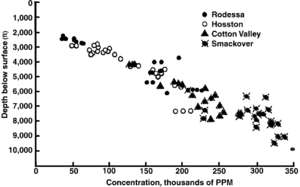
Water density is a function of its TDS concentration. The hydrostatic pressure at any depth is a function of TDS concentration from the surface to that point. The plot in Figure 1 of TDS vs. depth is from southern Arkansas. It shows a gradual increase in TDS from the surface to about depth::2000 ft, probably due to meteoric effects, and then a linear, more rapid increase in TDS from 2000 to depth::10,000 ft. Generally, below the depth of meteoric water influence, the increase in TDS in connate brines is linear and ranges from 25,000 to 100,000 mg/1 per depth::1000 ft (80 to 300 mg/1 per m).[1] There are exceptions to this general case.
Such consistent salinity increase with depth is not unique to the East Texas basin but is characteristic of most basins.


