Difference between revisions of "Magnetics: interpreting residual maps"
Cwhitehurst (talk | contribs) |
Cwhitehurst (talk | contribs) m (added Category:Treatise Handbook 3 using HotCat) |
||
| (22 intermediate revisions by 2 users not shown) | |||
| Line 6: | Line 6: | ||
| part = Predicting the occurrence of oil and gas traps | | part = Predicting the occurrence of oil and gas traps | ||
| chapter = Using magnetics in petroleum exploration | | chapter = Using magnetics in petroleum exploration | ||
| − | | frompg = 14- | + | | frompg = 14-13 |
| − | | topg = 14- | + | | topg = 14-15 |
| author = Edward A. Beaumont, S. Parker Gay | | author = Edward A. Beaumont, S. Parker Gay | ||
| link = http://archives.datapages.com/data/specpubs/beaumont/ch14/ch14.htm | | link = http://archives.datapages.com/data/specpubs/beaumont/ch14/ch14.htm | ||
| Line 14: | Line 14: | ||
| isbn = 0-89181-602-X | | isbn = 0-89181-602-X | ||
}} | }} | ||
| − | + | ||
| + | [[file:using-magnetics-in-petroleum-exploration_fig14-5.png|300px|thumb|{{figure number|1}}Geologic map of an area of crystalline [[basement]] in central Wisconsin on the southern edge of the Canadian Shield. From LaBerge;<ref>LaBerge, G. L., 1976, Major structural lineaments in the Precambrian of central Wisconsin: Proceedings of the First International Conference on the New Basement Tectonics, Utah Geological Assoc., p. 508–518.</ref> courtesy International Basement Tectonics Assoc.]] | ||
| + | |||
| + | A major pitfall in interpreting magnetic residual maps is assuming that magnetic highs and lows are caused by elevation changes on basement rocks in a sedimentary basin. To the contrary, most magnetic anomalies are caused by lithologic changes and the corresponding changes in susceptibility. As shown in [[:file:using-magnetics-in-petroleum-exploration_fig14-5.png|Figure 1]], the basement is of complex lithology and is highly fractured. The fractures divide the basement into blocks and are zones of weakness along which faults occur. The most important and most reliable information obtainable from aeromagnetic maps is the configuration (in plan view) of the underlying basement fault block pattern. | ||
==Interpreting depth to basement== | ==Interpreting depth to basement== | ||
| − | It is futile to attempt to define accurately the vertical dimension, Z, of adjacent source bodies with [[magnetics]] because of the inherent ambiguity of potential field methods in determining Z | + | It is futile to attempt to define accurately the vertical dimension, Z, of adjacent source bodies with [[magnetics]] because of the inherent ambiguity of potential field methods in determining Z.<ref name=ch14r8>Skeels, D. C., 1947, Ambiguity in gravity interpretation: Geophysics, vol. 12, p. 43–56., 10., 1190/1., 1437295</ref> Furthermore, seismic and subsurface methods measure depth so much more accurately than magnetics that it is unwise to try to compete with these excellent techniques. This is not to say, however, that we should not use magnetics to estimate the approximate thickness of the sedimentary section in a new basin, i.e., in determining whether it is 2, 5, or [[length::10 km]] thick, for example, to a usual accuracy of about ±15% under favorable conditions. |
==Interpreting fault throw== | ==Interpreting fault throw== | ||
| − | There is a fairly reliable way to determine the direction of throw of certain basement faults from magnetic maps. Faults that vertically offset basement or other magnetic sources generally show abrupt amplitude changes of magnetic anomalies, both the highs and lows. In | + | |
| + | [[file:using-magnetics-in-petroleum-exploration_fig14-9.png|300px|thumb|{{figure number|2}}A series of four northeast-trending magnetic anomalies on the west (two highs, two lows) abruptly loses amplitude along a northwest-trending line (A–A′) that crosscuts them.]] | ||
| + | |||
| + | There is a fairly reliable way to determine the direction of throw of certain [[basement]] faults from magnetic maps. Faults that vertically [[offset]] basement or other magnetic sources generally show abrupt amplitude changes of magnetic anomalies, both the highs and lows. In [[:file:using-magnetics-in-petroleum-exploration_fig14-9.png|Figure 2]], a series of four northeast-trending magnetic anomalies on the west (two highs, two lows) abruptly loses amplitude along a northwest-trending line (A–A′) that crosscuts them. The high and low magnetic trends can be identified easily on both sides of this obvious down-to-the-east fault. The four anomalies disappear altogether along another northwest-trending line farther east (B–B′). This may be a strike-slip fault, which is not common in this area, or another down-to-the-east fault that has down-dropped the four anomalies beneath the level of detection—the preferred interpretation. | ||
==Interpreting shear zones== | ==Interpreting shear zones== | ||
| − | [[file:using-magnetics-in-petroleum-exploration_fig14- | + | [[file:using-magnetics-in-petroleum-exploration_fig14-10.png|300px|thumb|{{figure number|3}}Residual aeromagnetic map of an area on the north shelf of the Anadarko basin in Oklahoma where the sedimentary section is approximately 3.6 km (12,000 ft) thick and basement lies about 3.8 km (12,500 ft) beneath flight level.]] |
| − | [[:file:using-magnetics-in-petroleum-exploration_fig14- | + | |
| + | [[:file:using-magnetics-in-petroleum-exploration_fig14-10.png|Figure 3]] shows a residual aeromagnetic map of an area on the north shelf of the Anadarko basin in Oklahoma where the sedimentary section is approximately 3.6 km (12,000 ft) thick and basement lies about 3.8 km (12,500 ft) beneath flight level. The residual magnetic contours (a) are shown at a 2-nT interval. The interpreted shear zones are traced along the linear gradients separating the residual magnetic highs and lows and along truncation lines of anomalies. On the right figure (b), two faults located from subsurface mapping are shown, labeled U/D. The evidence for their existence is seen in subsurface mapping. Both are located exactly along the interpreted basement shear zones, or block boundaries, as represented by gradients on the magnetic map. Note, however, that most of the interpreted basement shear zones in this area have no corresponding overlying faults. These zones were never reactivated—at least not sufficiently enough to be detected by the existing subsurface data. | ||
==Oil field example== | ==Oil field example== | ||
| − | + | In [[:file:using-magnetics-in-petroleum-exploration_fig14-10.png|Figure 3]], also note the structural high apparent in Devonian strata about [[length::800 m]] (2500 ft) above [[basement]] in the West Campbell field, conveniently nestled between block boundaries. Block boundaries, i.e., shear zones, generally erode low, so it follows that the interiors of blocks must, in many cases, correspond to basement topographic highs. West Campbell field appears to be a case in point and is most likely underlain by such a basement topographic prominence, although there are no wells to basement here to document it. The culmination of structural closure nearer the north end of the block rather than at its center is probably due to the south [[dip]] of basement in this area. | |
| − | |||
| − | In [[:file:using-magnetics-in-petroleum-exploration_fig14-10.png|Figure | ||
==Interpreting fault location== | ==Interpreting fault location== | ||
| − | [[file:using-magnetics-in-petroleum-exploration_fig14-11.png|thumb|{{figure number| | + | [[file:using-magnetics-in-petroleum-exploration_fig14-11.png|300px|thumb|{{figure number|4}}Residual magnetic map of another area in northern Oklahoma with faults superimposed. Details from Gatewood.<ref name=ch14r2>Gatewood, L., 1983, Viola–Bromide and Oil Creek Structure (map): Oklahoma City, privately sold and distributed.</ref>]] |
| − | [[:file:using-magnetics-in-petroleum-exploration_fig14-11.png|Figure | + | [[:file:using-magnetics-in-petroleum-exploration_fig14-11.png|Figure 4]] is a residual magnetic map of another area in northern Oklahoma with faults superimposed. Here the sedimentary section is approximately [[length::2 km]] (6500 ft) thick, and the flight level was about [[length::2.3 km]] (7500 ft) above basement. The faults shown were interpreted from a detailed subsurface study by Geomap Inc. The faults were mapped about [[length::500 m]] (1600 ft) above basement and show 30–90 m (100–300 ft) of displacement. Note the high degree of correlation between these faults and the residual magnetic gradients corresponding to the interpreted basement shear zones. Some 64% of the total length of faults, in fact, lies on the predicted shear zones following magnetic gradients. Note also that many magnetic gradients in Figure 14-11 show no faults cutting the section. These may not have been reactivated. |
==See also== | ==See also== | ||
| − | * [[ | + | * [[Magnetics: total intensity and residual magnetic maps]] |
* [[Basement fault blocks and fault block patterns]] | * [[Basement fault blocks and fault block patterns]] | ||
| − | * [[ | + | * [[Magnetic field: local variations]] |
| − | * [[ | + | * [[Magnetics: petroleum exploration applications]] |
==References== | ==References== | ||
| Line 54: | Line 59: | ||
[[Category:Predicting the occurrence of oil and gas traps]] | [[Category:Predicting the occurrence of oil and gas traps]] | ||
[[Category:Using magnetics in petroleum exploration]] | [[Category:Using magnetics in petroleum exploration]] | ||
| + | [[Category:Treatise Handbook 3]] | ||
Latest revision as of 17:41, 24 January 2022
| Exploring for Oil and Gas Traps | |

| |
| Series | Treatise in Petroleum Geology |
|---|---|
| Part | Predicting the occurrence of oil and gas traps |
| Chapter | Using magnetics in petroleum exploration |
| Author | Edward A. Beaumont, S. Parker Gay |
| Link | Web page |
| Store | AAPG Store |
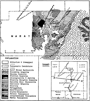
A major pitfall in interpreting magnetic residual maps is assuming that magnetic highs and lows are caused by elevation changes on basement rocks in a sedimentary basin. To the contrary, most magnetic anomalies are caused by lithologic changes and the corresponding changes in susceptibility. As shown in Figure 1, the basement is of complex lithology and is highly fractured. The fractures divide the basement into blocks and are zones of weakness along which faults occur. The most important and most reliable information obtainable from aeromagnetic maps is the configuration (in plan view) of the underlying basement fault block pattern.
Interpreting depth to basement
It is futile to attempt to define accurately the vertical dimension, Z, of adjacent source bodies with magnetics because of the inherent ambiguity of potential field methods in determining Z.[2] Furthermore, seismic and subsurface methods measure depth so much more accurately than magnetics that it is unwise to try to compete with these excellent techniques. This is not to say, however, that we should not use magnetics to estimate the approximate thickness of the sedimentary section in a new basin, i.e., in determining whether it is 2, 5, or length::10 km thick, for example, to a usual accuracy of about ±15% under favorable conditions.
Interpreting fault throw
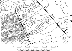
There is a fairly reliable way to determine the direction of throw of certain basement faults from magnetic maps. Faults that vertically offset basement or other magnetic sources generally show abrupt amplitude changes of magnetic anomalies, both the highs and lows. In Figure 2, a series of four northeast-trending magnetic anomalies on the west (two highs, two lows) abruptly loses amplitude along a northwest-trending line (A–A′) that crosscuts them. The high and low magnetic trends can be identified easily on both sides of this obvious down-to-the-east fault. The four anomalies disappear altogether along another northwest-trending line farther east (B–B′). This may be a strike-slip fault, which is not common in this area, or another down-to-the-east fault that has down-dropped the four anomalies beneath the level of detection—the preferred interpretation.
Interpreting shear zones
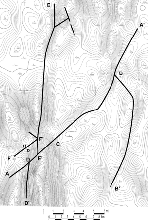
Figure 3 shows a residual aeromagnetic map of an area on the north shelf of the Anadarko basin in Oklahoma where the sedimentary section is approximately 3.6 km (12,000 ft) thick and basement lies about 3.8 km (12,500 ft) beneath flight level. The residual magnetic contours (a) are shown at a 2-nT interval. The interpreted shear zones are traced along the linear gradients separating the residual magnetic highs and lows and along truncation lines of anomalies. On the right figure (b), two faults located from subsurface mapping are shown, labeled U/D. The evidence for their existence is seen in subsurface mapping. Both are located exactly along the interpreted basement shear zones, or block boundaries, as represented by gradients on the magnetic map. Note, however, that most of the interpreted basement shear zones in this area have no corresponding overlying faults. These zones were never reactivated—at least not sufficiently enough to be detected by the existing subsurface data.
Oil field example
In Figure 3, also note the structural high apparent in Devonian strata about length::800 m (2500 ft) above basement in the West Campbell field, conveniently nestled between block boundaries. Block boundaries, i.e., shear zones, generally erode low, so it follows that the interiors of blocks must, in many cases, correspond to basement topographic highs. West Campbell field appears to be a case in point and is most likely underlain by such a basement topographic prominence, although there are no wells to basement here to document it. The culmination of structural closure nearer the north end of the block rather than at its center is probably due to the south dip of basement in this area.
Interpreting fault location

Figure 4 is a residual magnetic map of another area in northern Oklahoma with faults superimposed. Here the sedimentary section is approximately length::2 km (6500 ft) thick, and the flight level was about length::2.3 km (7500 ft) above basement. The faults shown were interpreted from a detailed subsurface study by Geomap Inc. The faults were mapped about length::500 m (1600 ft) above basement and show 30–90 m (100–300 ft) of displacement. Note the high degree of correlation between these faults and the residual magnetic gradients corresponding to the interpreted basement shear zones. Some 64% of the total length of faults, in fact, lies on the predicted shear zones following magnetic gradients. Note also that many magnetic gradients in Figure 14-11 show no faults cutting the section. These may not have been reactivated.
See also
- Magnetics: total intensity and residual magnetic maps
- Basement fault blocks and fault block patterns
- Magnetic field: local variations
- Magnetics: petroleum exploration applications
References
- ↑ LaBerge, G. L., 1976, Major structural lineaments in the Precambrian of central Wisconsin: Proceedings of the First International Conference on the New Basement Tectonics, Utah Geological Assoc., p. 508–518.
- ↑ Skeels, D. C., 1947, Ambiguity in gravity interpretation: Geophysics, vol. 12, p. 43–56., 10., 1190/1., 1437295
- ↑ Gatewood, L., 1983, Viola–Bromide and Oil Creek Structure (map): Oklahoma City, privately sold and distributed.


