Difference between revisions of "Magnetics: petroleum exploration applications"
Cwhitehurst (talk | contribs) m (removed Category:Methods in Exploration 10 using HotCat) |
Cwhitehurst (talk | contribs) m (added Category:Treatise Handbook 3 using HotCat) |
||
| Line 81: | Line 81: | ||
[[Category:Predicting the occurrence of oil and gas traps]] | [[Category:Predicting the occurrence of oil and gas traps]] | ||
[[Category:Using magnetics in petroleum exploration]] | [[Category:Using magnetics in petroleum exploration]] | ||
| + | [[Category:Treatise Handbook 3]] | ||
Latest revision as of 17:59, 24 January 2022
| Exploring for Oil and Gas Traps | |

| |
| Series | Treatise in Petroleum Geology |
|---|---|
| Part | Predicting the occurrence of oil and gas traps |
| Chapter | Using magnetics in petroleum exploration |
| Author | Edward A. Beaumont, S. Parker Gay |
| Link | Web page |
| Store | AAPG Store |
Magnetics can be an extremely effective and economical exploration tool when properly employed. Its proper use, however, depends on the following:
- Avoiding several pitfalls described herein
- Integrating the magnetics with seismic, subsurface, and other data
- Developing the basement fault block pattern from the magnetic data
- Using concepts of basement control in working with all data sets
Applications
Magnetics can be applied to petroleum exploration for many reasons:
- Aiding 2-D and 3-D seismic interpretations
- Laying out new 2-D and 3-D seismic programs
- Aiding in exploration programs based primarily on subsurface (well) data
- Estimating depth to basement over broad areas
Interpreting fault location in seismic sections

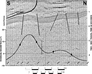
Magnetics can be very valuable in interpreting seismic data by plotting residual magnetic profiles along seismic sections. This technique is valuable in looking for (1) subtle stratigraphic changes that can occur along basement block boundaries and (2) subtle fault offsets or other structural and stratigraphic features. The locations of the basement weakness zones provide focal points for examining the seismic data more closely.
Figure 1 shows an example of a magnetic profile on an interpreted seismic section from Logan County, Arkansas. The dark band corresponds to Cambrian through Mississippian sedimentary rocks. Note correlation between the location of the four normal faults interpreted in the seismic section and the location of faults in the magnetic profile (marked by diamonds).
Developing leads from analogs
Magnetic basement mapping in petroleum exploration can be applied to the search for leads or prospects that can be quickly and economically developed by comparing known traps or structure (and/or stratigraphy) with the basement fault block pattern. Some areas have never been tested by the drill where the structure at basement level is analogous to that over nearby producing properties. Some of these leads become viable prospects when subjected to follow-up seismic profiling or other appropriate exploration techniques. A common type of structural or stratigraphic data used to correlate to the magnetic data is subsurface mapping, developed from well data. However, on overseas projects or in frontier areas, the best (or only) data available may be 2-D seismic surveying. In either case, the procedure is to search for “look-alikes” on the magnetic data that correspond to features over known producing fields. Since the magnetic data can be acquired in continuous fashion over large areas at a very economical price, many good leads can be developed in a short time.
Laying out seismic programs

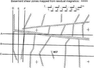
Suppose we have developed a basement fault block pattern as shown in Figure 2. Also suppose this area has been tectonically active and is characterized by a fair degree of faulting. This being the case, we can expect that many of the basement shear zones have been reactivated and are now the locus of faults and fractures in the sedimentary section. Thus, A, D, and F in Figure 2 are the wrong places to run 2-D seismic lines because of the probable poor seismic definition due to fracturing along these zones and the possibility of sideswipe. Lines B, C, and E, on the other hand, are good places to run seismic surveys because of the probable lack of fracturing and faulting at these localities. In addition, gravitational compaction structures are generally found within these blocks; thus, line B or C would have found West Campbell field (WCF) but Line A would not.
Interpreting fault location in map view

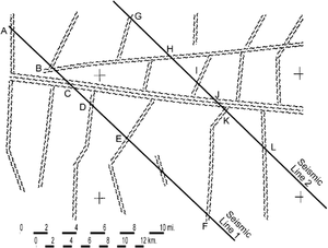
Magnetics can be quite useful in interpreting existing seismic programs after they have been shot. In Figure 3, two 2-D seismic lines have been placed purposely in the worst possible positions relative to the basement fault block pattern.
Assuming all the basement shear zones represent faults in the sedimentary section, then “hooking-up” the faults in this area is a problem. Fault pick C on line 1, for example, does not connect straight across to fault pick G on line 2, nor even to H or I, which are some distance away. Instead, it hooks up to J, making this fault very oblique to the seismic lines. This is not a very common way of connecting faults on most seismic interpretations. The connection of B to H is straightforward but, again, is diagonal to the seismic lines, whereas F–K runs diagonally in the opposite direction. Fault picks D, G, E, and I do not connect to the other seismic line at all; they terminate somewhere in between.
Depth estimates
Depth estimates from aeromagnetic data can determine values for broad areas, such as the approximate thickness of the sedimentary section in a basin or at a limited number of points within the basin. Using depth estimates to distinguish between the depths of adjacent magnetic anomalies invites trouble.
Magnetics vs. other techniques
We might question the strong emphasis on magnetics for mapping the basement fault block pattern. However, is there any other way to reliably map this pattern beneath the sedimentary section? Methods that depend on surface information—Landsat, SLAR, conventional photo geology, and surface geology—are of limited value. That leaves only gravity and seismic techniques.
However, gravity techniques generally do not separate adjacent basement blocks because of the lack of density contrast between adjacent blocks and because of interference from density differences within the sedimentary section. On seismic data, the basement reflector is often difficult to recognize beneath complex structure and because of a lack of velocity contrast with the dense dolomites that overlie the basement in many areas. Furthermore, both seismic and gravity methods are expensive to apply over broad areas and cannot provide even a tiny percentage of the area coverage that can be obtained with magnetics for the same price.
The conclusion is that both seismic and gravity are excellent follow-up tools for profiling, or “cross-sectioning,” specific leads developed from the basement fault block pattern by magnetics and are best used for this purpose.
See also
- Basement fault blocks and fault block patterns
- Magnetic field: local variations
- Magnetics: interpreting residual maps
- Magnetics
- Magnetics: total intensity and residual magnetic maps
References
- ↑ Coleman, J. M., and H. H. Roberts, 1991, Mississippi River depositional system: model for the Gulf Coast Tertiary, in D. Goldthwaite, ed., An Introduction to Central Gulf Coast Geology: New Orleans Geological Society, p. 99–121.
- ↑ 2.0 2.1 Piggott, N., and A. Pulham, 1993, Sedimentation rate as the control on hydrocarbon sourcing, generation, and migration in the deepwater Gulf of Mexico: Proceedings, Gulf Coast Section SEPM 14th Annual Research Conference, p. 179–191.