Difference between revisions of "Interpreting gravity measurements"
FWhitehurst (talk | contribs) |
FWhitehurst (talk | contribs) |
||
| Line 24: | Line 24: | ||
|- | |- | ||
| 1 | | 1 | ||
| − | | Use well logs and outcrop data to make structural [[cross section]]s through critical areas containing gravity data to be interpreted. | + | | Use well logs and [http://www.merriam-webster.com/dictionary/outcrop outcrop] data to make structural [[cross section]]s through critical areas containing gravity data to be interpreted. |
|- | |- | ||
| 2 | | 2 | ||
Revision as of 22:25, 17 November 2014
| Exploring for Oil and Gas Traps | |

| |
| Series | Treatise in Petroleum Geology |
|---|---|
| Part | Predicting the occurrence of oil and gas traps |
| Chapter | Applying gravity in petroleum exploration |
| Author | David A. Chapin, Mark E. Ander |
| Link | Web page |
| Store | AAPG Store |
Procedure
The table below outlines a suggested procedure for interpreting gravity.
| Step | Action |
|---|---|
| 1 | Use well logs and outcrop data to make structural cross sections through critical areas containing gravity data to be interpreted. |
| 2 | Plot gravity profiles above structural cross sections and seismic sections. Add magnetic profiles if available. |
| 3 | From geology interpreted from data, build gravity model sections. Divide the section into intervals of approximately the same density. |
| 4 | Calculate a predicted gravity profile. Check the observed profile against the calculated profile. Where differences exist, adjust the gravity model and recalculate the gravity profile until a suitable match between observed and calculated is made. |
| 5 | Check the interpretation of the gravity map, i.e., location of faults, against the model profiles and all other available data. |
Interpreting structure
In many places in the world, structural highs have higher density and are expressed in the data as gravity highs because dense basement rocks are closer to the surface. Therefore, a gravity map often is used directly as a pseudostructure map. However, there is not a one-to-one relationship between milligals and depth; therefore, the map must be viewed in a qualitative sense as a formline map. There are exceptions, as well, where structural highs are gravity lows because dense basement rocks are not closer to the surface. These structures may be of lower density than the surrounding rocks.
Rock densities
The range of densities for all rock types (igneous, metamorphic, and sedimentary) is typically 1.60–3.20 g/cm3. The density values of sedimentary rocks typically range from 1.80 to 2.80 g/cm3. Thus, small variations of density in sedimentary rocks may be invisible to the method. A5–10% error in estimating subsurface densities from gravity is quite common. This is in contrast to magnetics, where typically there are orders of magnitude variations in susceptibilities.
Horizontal layers
Horizontal layers have no anomalous gravity response. Thus, it is impossible to determine the subsurface density distribution if there are no lateral changes. Layer-cake geology yields no anomalous gravity signal. A bed is considered infinite and horizontal if it is about five times wider in all directions than it is thick, with no dip.
Interpretation ranges
Gravity interpretation can produce a range of answers. The better the geologic and geophysical constraints, the better the interpretation. A completely unconstrained interpretation produces several acceptable answers that can all produce the identical anomaly. While it is often easy to rule out certain classes of interpretations as geologically unreasonable, it is best to start with good constraints or to test reasonable geologic questions.
Depth-to-basement determination
Gravity is not as good at depth-to-basement or depth-to-density anomaly estimations as other geophysical methods. Though possible to do, it is often difficult to determine the appropriate depth to geologic source unless other constraints exist.
Positions of geologic bodies
Gravity is particularly good at locating horizontal positions of geologic bodies that have a different density than the surrounding rock—ore bodies or salt-cored bodies, for example.
Interpreting fault location
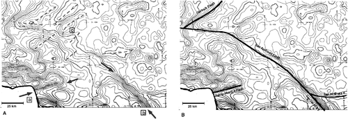
Faults usually can be identified through either steep gradients or truncation of trends.
Figure 1 contains two Bouguer gravity maps of Southern California, showing the expression of faults. In the left map, locations a and b show strong gradients, which indicate faults. A series of truncated trends (dashed) near location c also indicate faults. Figure 1B shows the actual location of the major faults over the same gravity map.
