Drilling a well
How wells are drilled[edit]
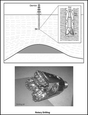
The most common method of drilling wells uses rotary drilling[1] (Figure 1). A drilling bit is attached to the end of a long string of jointed, hollow drill pipe, and the whole assembly is rotated by a motorized turntable at the surface, the rotary table. Modern rigs use a top drive system for rotating the drill pipe, an assembly that is guided up and down rails on the derrick. The rotating bit cuts or crushes the rock. Drilling mud, consisting of water or an oil-water mixture, solids, and various additives, is circulated down through the drill pipe and out through nozzles in the drilling bit. The mud returns to the surface up the annulus, the space outside of the drill pipe. The mud lubricates the bit, prevents it from getting too hot because of friction, and lifts the drilled rock cuttings up the hole. It should be dense enough to overbalance any high-pressure formations encountered while drilling. If it fails in this last action, the fluid in the formation will displace the mud up the hole. This is called a kick. Should this hazardous situation not be dealt with quickly, hydrocarbons will exit at the surface and a blowout results. Scenes of oilmen dancing with glee as oil gushes over the drilling rig are for the cinema only. In reality, oil field professionals are acutely aware of the danger involved in the combustion and explosive blast that can result from a hydrocarbon blowout.

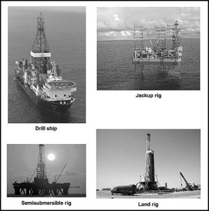
The scale and cost of a drilling operation differs between wells onshore and those offshore. An onshore well is drilled with a relatively cheap land rig (Figure 2); offshore, the operation is several times more expensive.
In shallow water, typically about 6–45 m (20–150 ft) deep, drilling is conducted by a jackup rig. A jackup is a rig that has three or more legs that sit on the sea floor. In moderately deep water (more than 45 m [150 ft] deep), a floating or semisubmersible rig is used. The semisubmersible rig is kept in place by several anchors.[2]
In deep water, a drill ship is the preferred option. Deep water is defined as water depths between 500 and 2000 m (1640 and 6562 ft).[3] The drill ship is maintained in place by dynamic positioning. Computers constantly calculate the position of the drill ship using global positioning system technology or in response to signals from transducers on the sea bed. Signals are sent to propellers and lateral thrusters on the sides of the vessel. These readjust the location of the ship to keep it stable against the forces of wind and water currents.
Drilling operation[edit]
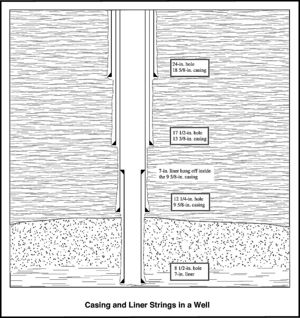
A well starts by being spudded as the drill bit encounters the first bit of soil or subsea sediment. A well will not be drilled all the way through in one go; instead, there will be several stages of drilling. Each section will involve drilling the hole to a certain depth and then running in and cementing metal casing onto the rock surface of the borehole wall before going any farther (Figure 3). The simplest reason for doing this is to prevent poorly consolidated sediment from collapsing once the well has been drilled over a long interval, although there may also be good reasons for isolating certain problem formations.
A typical well will have a similar geometry to an inverted telescope, with the hole size and casing diameter decreasing incrementally down the hole. Typical hole sizes and casing diameters are 36-in. (91.44-cm) hole, 24-in. (60.96-cm) hole, cased with 18 5/8-in. (47.29-cm) or 20-in. (50.8-cm) casing; 17 1/2-in. (44.45-cm) hole, cased with 13 3/8-in. (33.95-cm) casing; 12 1/4-in. (31.11-cm) hole, cased with 9 5/8-in. (24.43-cm) casing; and 8 1/2-in. (21.59-cm) hole, cased with a 7-in. (17.78-cm) liner. A liner is a type of casing that is not run all the way up the hole; instead, it is hung off inside the lower part of a casing string (Figure 3).
It is necessary to change out the bit frequently because it will become worn and inefficient after several days of drilling. When this happens, the entire drill pipe needs to be pulled out of the wellbore and then run in with a new bit attached. This operation is known as tripping. A two-way trip, or round trip, can take 12 hr or more in the deeper sections of the well.
Specialist service personnel called mud loggers monitor the drilling parameters and collect the drill cuttings for analysis. There may also be a well site geologist present at the rig site who will draw up a lithology log from examination of the cuttings. The objective is to analyze the lithostratigraphy of the interval being drilled in order to help make operational decisions, such as when to run casing. The well site geologist will also examine the cuttings for indications of hydrocarbon shows. An ultraviolet light source will be used to check for hydrocarbon fluorescence in the samples, a sign that oil is present.
Sometimes the subsurface team will require the reservoir interval to be cored. This is carried out with a special coring barrel attached to the end of the drilling assembly once the drill bit has been removed. A doughnut shaped coring head will cut a cylinder of reservoir rock, and the cut core will slide into the coring barrel, typically about 18–27 m (60–90 ft) long. Once full, the core barrel is pulled back up to the surface for retrieval. Several coring trips may be required to core a reservoir interval of interest. Given the trip time for coring and the expensive rig day rates, a coring operation is costly.[4]
Drilling problems[edit]
Occasionally, something will go wrong and a piece of equipment is lost down the well. For example, the drill pipe may twist off somewhere along its length and fall to the bottom of the hole. The drilling operation will come to a halt unless the foreign object or fish, as it is known, is "fished" out; that is, physically removed from the hole.[5] Specialist tools are available for fishing operations. Sometimes the fishing operation can last many days.
Every now and again, the hole will collapse in on itself. This will happen where the earth stresses exceed the rock strength. Salt sections or shale sections at shallow depths containing water-sensitive clays are prone to this. Water-sensitive clays can expand by reacting with drilling fluids, particularly low salinity muds. This can cause the borehole wall to founder and bury the drill bit irretrievably. A decision may then be made to branch off from what hole is left, and this is called sidetracking.
Another problem that can occur is lost circulation, whereby the drilling mud is lost in large quantities into a fracture or a highly permeable interval. Adding fibrous material to the mud will solve the problem. This clogs up the lost circulation zone and prevents any further losses.
Well operations after drilling has ceased[edit]
Once the reservoir has been drilled through, the drilling operation will come to a stop. The end of the well is called the total depth or TD for short. At this point, the drill pipe is pulled out and wireline logs may be run. Wireline logs are measuring tools run on the end of a long cable that record variations in the physical properties of the reservoir rock and fluids behind the borehole. It is possible to build up a detailed picture of the reservoir lithologies and fluids based on an analysis of the various types of log response. For instance, some wireline logs will allow the porosity of the reservoir interval to be determined. Porosity is the fraction or percentage of the volume of void space in the rock relative to the whole rock volume.
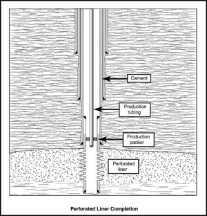
Sometimes the well results are so poor that the well is plugged and abandoned. The well is not required for production and has no further use. To avoid any hydrocarbons leaking to the surface, the well is isolated by cement plugs. However, if the wireline logs indicate that the well is likely to produce an economically significant volume of hydrocarbons, then it will be completed. In a typical production well, the reservoir will be isolated behind casing or a liner. The annulus between the rock and the liner is filled with cement. This means that it is possible to perforate, that is punch holes in, the liner such that a specific interval in the reservoir can be accessed for production or injection[6] (Figure 4). Alternatively, a preslotted liner can be used, or, in hard competent rocks such as limestones, the hole can be left open. This latter practice is sometimes referred to as a barefoot completion.
Production tubing will then be installed in the well. This is a narrow-diameter pipe, which isolates the produced hydrocarbons from the rest of the well on the way up to the surface. The diameter of the tubing can be matched to the optimal flow rate for the producing fluids.
On occasions, the production rate from a new well will be less than expected; techniques are available for improving the production rate when this happens. The reservoir rock can be hydraulically fractured by injection of fluids at a high rate into the wellbore. Some reservoirs can be acidized by adding acids to dissolve any acid-soluble material in the near wellbore area. This can locally improve the permeability, the rock's capacity to flow. Acidization can be particularly effective in increasing the near-wellbore permeability of carbonate reservoirs and sandstone reservoir rock with carbonate or acid-soluble cements.[7]
On completion, the well is tied into the production train and brought on stream. An excellent initial production rate for an offshore well is about 20,000 barrels per day; a barrel is equivalent in volume to 0.159 m3 (5.6 ft3). The fluids are produced through a separator, a large piece of apparatus for splitting up the produced fluids into oil, gas, water, and unwanted solids.[8]
Later on in the life of a well, there may be reasons for making an intervention in the well, for instance to run production logs. These can be used to get information on the source of water ingress into a production well. Many wells produce water along with oil. Water mixing in with the lighter oil as it flows to the surface will increase the density of flowing fluids within the tubing, and the production rate will fall. The water-producing perforations can be shut off by running an isolation plug in the well.
Wells can also be worked over. This involves repairing the pipework or equipment in a well, or carrying out an operation to improve the productivity of a production well. For instance, the engineers may want to install a gas lift system in a production well. Gas is injected into the upper part of the wellbore and then through valves in the production tubing. This reduces the density of the producing fluid column and increases the flow rate. The gas will expand as it moves up through the tubing providing additional lift.[9]
See also[edit]
- Drilling fluid
- Drilling problems
- Land rigs
- Offshore rigs
- Conventional coring
- Fishing
- Well completions
- Stimulation
- Surface production equipment
- Artificial lift
References[edit]
- ↑ Rabia, H., 1985, Oilwell drilling engineering, principles and practice: London, Graham & Trotman, 400 p.
- ↑ Reed, B., 1992, Offshore rigs, in D. Morton-Thompson and A. M. Woods, eds., Development geology reference manual: AAPG Methods in Exploration Series 10, p. 65-66.
- ↑ Weimer, P., and R. M. Slatt, 2004, Petroleum systems of deep-water settings: Society of Exploration Geophysicists/European Association of Geoscientists and Engineers Distinguished Instructor Series 7, 465 p.
- ↑ Whitebay, L., 1992, Conventional coring, in D. Morton-Thompson and A. M. Woods, eds., Development geology reference manual: AAPG Methods in Exploration Series 10, p. 115-118.
- ↑ Woods, A. M., 1992, Fishing, in D. Morton-Thompson and A. M. Woods, eds., Development geology reference manual: AAPG Methods in Exploration Series 10, p. 83-86.
- ↑ Holditch, S. A., 1992, Well completions, in D. Morton-Thompson and A. M. Woods, eds., Development geology reference manual: AAPG Methods in Exploration Series 10, p. 463-468.
- ↑ Gidley, J. L., 1992, Stimulation, in D. Morton-Thompson and A. M. Woods, eds., Development geology reference manual, AAPG Methods in Exploration Series 10, p. 469-473.
- ↑ Jennings, J., 1992, Surface production equipment, in D. Morton-Thompson and A. M. Woods, eds., Development geology reference manual: AAPG Methods in Exploration Series 10, p. 485-487.
- ↑ Smallwood, D. D., 1992, Artificial lift, in D. Morton-Thompson and A. M. Woods, eds., Development geology reference manual: AAPG Methods in Exploration Series 10, p. 458-497.


