File:M115CH10FG05.jpg
Jump to navigation
Jump to search

Size of this preview: 800 × 583 pixels. Other resolutions: 320 × 233 pixels | 1,281 × 934 pixels.
Original file (1,281 × 934 pixels, file size: 1.29 MB, MIME type: image/jpeg)
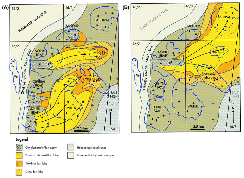
Simplified schematic map showing the depositional extent of the (A) South Brae and (B) North Brae submarine fan lobes within the Brae depositional system. Note that the South Brae and North Brae submarine fans correspond to the Brae 2 and Brae 1 intervals, respectively. Modified from Turner and Connell (1991) and Spence and Kreutz (2003). From AAPG Memoir 115—Rift-Related Coarse-Grained Submarine Fan Reservoirs: The Brae Play, South Viking Graben, North Sea, Chapter 10.
File history
Click on a date/time to view the file as it appeared at that time.
| Date/Time | Thumbnail | Dimensions | User | Comment | |
|---|---|---|---|---|---|
| current | 18:44, 17 January 2019 | | 1,281 × 934 (1.29 MB) | Molyneux (talk | contribs) | Simplified schematic map showing the depositional extent of the (A) South Brae and (B) North Brae submarine fan lobes within the Brae depositional system. Note that the South Brae and North Brae submarine fans correspond to the Brae 2 and Brae 1 interv... |
You cannot overwrite this file.
File usage
The following page uses this file: