Marine seismic data acquisition
| Development Geology Reference Manual | |

| |
| Series | Methods in Exploration |
|---|---|
| Part | Geophysical methods |
| Chapter | Marine seismic data acquisition |
| Author | James F. Desler |
| Link | Web page |
| Store | AAPG Store |
Marine seismic data acquisition techniques and capabilities have advanced at a rapid pace over the past few years. Today the typical marine seismic source is much more powerful, efficient, and effective due to improvements in towing technology, air gun array design, and the air guns themselves. Towing two parallel streamer cables in three-dimensional surveys is now the rule rather than the exception, and recording between 240 and 480 channels of seismic data is common. The ability to determine the position of everything in the water on a shot-by-shot basis has also improved significantly.
Source
Over the years, a large variety of different marine seismic energy sources have been used, but today two sources are used for almost all of the marine seismic shot. These are the air gun and the water gun, with the air gun being by far the most common.
In a water gun, a piston is driven through the water so fast that a vacuum bubble is produced. When this bubble collapses, acoustic energy is radiated. The pressure signature from a water gun has pressure variations (a precursor) before the main pressure pulse. This precursor is caused by the initial acceleration of the water, and special water gun processing (signature deconvolution) must be performed. Geophysical contractors who use water guns have developed this special processing.
In an air gun, high pressure air (typically 2000 psi) is stored in a chamber, and upon receipt of a firing command, this air is expelled into the water. This release of air generates a strong pressure pulse and forms an air bubble. This bubble oscillates, generating a sequence of decaying pressure variations (bubble train) that follow the initial pulse. Air gun arrays are designed using air guns that hold differing amounts of air, so that the bubble oscillations are of different periods and therefore tend to cancel one another while the initial pulses reinforce. Thus, a signal approaching an impulse is generated because the primary objective of seismic method is to measure the acoustic impulse response of the earth.
Recently, sleeve guns, which are designed to be more efficient and reliable than conventional air guns, have been introduced. A disadvantage of the sleeve gun is that it is currently offered in only a few discrete sizes, which handicaps the air gun array designer. Clustered guns are another recent advancement. When two or three air guns are fired in close vicinity of one another, it is possible to get a strong initial pulse and a weak bubble sequence because the composite bubble formed is not spherical and thus does not tend to support oscillations.
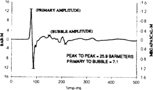
The output of an air gun array is typically illustrated by a normalized pressure time sequence called a signature. The signature of a 1000-in.3 air gun subarray is shown in Figure 1. One measure of the strength of the source is the peak-to-peak pressure, which is often quoted in pressure units of bars at length::1 m (bar meters). Another measure of the performance of the array is the peak-to-bubble ratio, which is the peak-to-peak magnitude of the initial pulses divided by the magnitude of the residual bubble oscillations. These simplistic measures of performance can be used to compare different sources provided the signatures have been recorded using the same techniques, especially the same field filters[1].
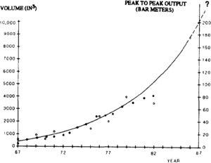
The strength of marine seismic sources has increased at a steady pace over the past 20 years, as shown in Figure 2. Stronger sources produce detectable signals from deeper reflectors. Very large air compressors are necessary to charge the air guns, which typically fire every 10 sec. In addition to increased strength, air gun arrays consisting of six, eight, or ten subarrays (strings) are deployed in various geometries to improve directivity and/or to reduce shot generated noise. The simple wide array is common and very effective[2].
Receiver
The basic element used to detect the reflected seismic energy is the hydrophone, a piezoelectric device that creates an electrical signal in response to pressure changes. Multiple hydrophones are mounted in a streamer cable, which is a jacketed tube filled with a liquid less dense than water. Weights and liquid are combined so that the streamer cable is near neutral buoyancy. Then, with the help of depth-controlling devices called birds, the cable can be positioned at a specified depth below the surface of the water. Achieving neutral buoyancy is called balancing the cable.
Multiple hydrophones mounted throughout a certain length of the streamer cable are electrically connected in series and parallel so as to form what is called a detector array, a station, or a group. Typically, a group is length::25 m in length and contains from 25 to 40 hydrophones. Group lengths range from 6.25 to length::50 m. It is common to put two, three, or four groups in a cable section (75 to length::100 m long), which is a unit with connectors at each end. When a section is damaged or fails for any reason, it can easily be replaced.
The length of a streamer cable ranges from 3000 to depth::6000 m. Shorter cables can be deployed in areas with obstructions to improve control and thereby avoid damage. The length of cable required for a job depends on the objectives of the survey. In general, the deeper the objective, the longer the cable should be. A rule of thumb is that x, the length of the cable, should equal z, the depth of the objective.
Some streamer cables contain electronics to convert the analog signal from the hydrophones to a digital form. These are called digital cables, while the traditional streamer cables are called analog cables. In an analog cable, there must be a pair of wires for each group. As the number of groups increases, the number and weight of the copper conductors increase, which necessitates that the diameter of cable gets larger and larger. There are analog cables with as many as 240 channels[3]. Digital cables, however, can multiplex data onto one or a few conductors, so there is not a weight problem due to conductors. Some digital cables have as many as 1000 channels. Analog cables may be more susceptible to electrical leakage, but a well-maintained analog cable can gather data equal in quality to that gathered using a digital cable.
In 3-D seismic surveys, the seismic boat commonly tows two and even three parallel cables spaced laterally apart so that two or three seismic lines are collected per traverse of the vessel. In a two-cable application with a single source, two seismic lines spaced L meters apart in the subsurface will be acquired if the streamer cables are spaced 2L apart.
Ghosting
The air-water interface reflects upcoming acoustic energy, a phenomenon referred to as ghosting. Due to ghosting, certain frequencies are destructively interfered with while other frequencies are boosted. The lowest frequency boosted by the maximum amount is calculated by dividing the velocity of sound in water (1500 m/sec) by four times the depth of the detector or the source. Therefore, a detector or source at a depth of length::10 m causes the 37.5-Hz component of the seismic signal to be emphasized. Odd multiples of this frequency are also boosted. The frequencies that are completely eliminated (notched) by ghosting are the even multiples of the frequency just calculated. The notch frequencies caused by a detector or source at length::10 m are 0, 75, 150, and so on. Thus, the depth of the source and the depth of the detector are important survey parameters.
It is essential that the precise location of the survey be known, and this is where navigation is important. The work horse of the industry, certainly in the Gulf of Mexico, is the shore-based navigation system Syledis. In the Gulf and in other areas, base stations have been placed on production platforms to extend the range of coverage. Another system, Star-Fix, uses commercial satellites and a shore-based network of stations to determine the position of the satellites precisely. Given this information, the position of the vessel can be calculated. Another satellite system is the Global Positioning System (GPS), which is now being installed by the U.S. government. It is still unclear whether its capabilities will be intentionally degraded for commercial applications. GPS (or differential GPS) has the potential to make all other navigation systems obsolete.
The advent of 3-D seismic has increased the demand for accuracy in positioning. One needs to know within a few meters the position of the source and the position of each detector group for every seismic shot. Underwater, acoustical systems and/or laser measurement through the air are used to determine the positions of things in the water near the vessel. Extremely accurate magnetic compasses are attached along the streamer cable, and sometimes a navigation receiver is placed in the tail buoy at the end of the streamer cable. Accuracies of a few meters are desirable.
Vessel
The ship that carries and tows the source and streamer cable and that houses the personnel needed to operate and repair everything must be fairly large and self contained. Currently, the ideal sized conventional seismic vessel is about length::250 ft (75 m) long. Comfortable living conditions are required to attract and keep qualified personnel. The electronic and mechanical systems on a seismic boat are complex, and when something breaks far out at sea, the people onboard need to be able to fix it.
Quality control
It is essential to have stringent but fair quality control (QC) specifications on each and every aspect of the marine seismic data acquisition system. Air guns will break. The QC specifications must address how many air guns can fail before acquisition must be terminated for repair. Things will go wrong with the streamer cable. How many channels can go bad before the cable must be repaired? Sometimes there are other seismic crews in the area. How much interference noise[4] can be tolerated?
The details of this very important subject are beyond the scope of this note, but in my opinion, it is almost as easy to keep things running at 90 to 100% capacity as it is to keep things running at 70 to 80%, so it makes sense to demand high performance.
Conclusions
We can expect marine seismic data acquisition technology to continue to advance. The objectives remain the same—get deeper penetration and higher resolution in a cost effective manner. The performance objectives—deeper penetration and higher resolution—will be achieved by increasing the signal to noise ratio. This is accomplished by increasing the signal and/or decreasing the noise.
Seismic data processing is important (see Basic seismic processing), and much of the increased signal to noise will be done on the computer, but only so much. When better data are acquired in the field, the final result will be better illumination of the exploration objectives.
See also
- Introduction to geophysical methods
- Seismic data acquisition on land
- Three-dimensional seismic method
- Basic seismic processing
References
- ↑ Johnston, R. C., D. H. Reed, and J. F. Desler, 1988, SEG standards for specifying marine seismic energy sources: Geophysics, v. 53, p. 566–575
- ↑ Lynn, W., and K. Larner, 1989, Effectiveness of wide marine seismic source arrays: Geophysical Prospecting, v. 37, p. 181–207.
- ↑ Carlini, A., and A. Mazzotti, 1989, Optimized receiver array simulation based upon resolution constraints: Geophysical Prospecting, v. 37, p. 607–621.
- ↑ Lynn, W., M. Doyle, K. Larner, and R. Marschall, 1987, Experimental investigation of interference from other seismic crews: Geophysics, v. 52, p. 1501–1524., 10., 1190/1., 1442268

