Fault seal analysis for reservoir development
An Entry from the AAPG 2021 Middle East Wiki Write Off!
by Alfian Gilang Gumelar, BitCan Geoscience & Engineering Inc.
Fault seal analysis is used to determine the level of connectivity of a separate reservoir due to fault segments. This is controlled by the permeability and porosity parameters of rocks that are in the fault section. Fault segment that becomes insulating if it has high porosity and permeability values will channel hydrocarbon fluid to the surface. So that the fault is one of the traps that are good for hydrocarbons. There is a mechanism where a fault can be a seal of fluid [1] [2]:

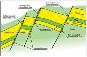
- Juxtaposition position alignment, where the sandstone reservoir is aligned with rocks that have low permeability (clay / shale) with high pressure (Figure 1).
- Clay smear, where the clay enters the fault plane and puts high pressure.
- Cataclastic, where sandstone is crushed so that the grains of sand material enter the fault plane with high capillary pressure.
- Diagenesis, where cementation that occurs in the partial fault plane / can also completely cover porosity so that the field becomes permeable.
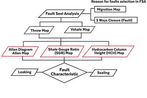
Fault Seal Analysis method has key factors that are vertical movement (throw) and shale or clay content (Vshale) in the rocks involved in faulting[4]. One method of quantity is the Shale Gouge Ratio (SGR) and Hydrocarbon Column Height (HCH) which will analyze fault characteristics (Figure 2).
Juxtaposition analysis
One of the mechanisms of the process of hydrocarbon insufficiency is juxtaposition. This barrier is caused by the presence of rocks that have different physical properties of rocks, namely permeability and porosity. Rocks that have greater permeability and porosity will not flow hydrocarbons in the direction of smaller permeability and porosity. If the sandstone is in contact with the claystone then a juxtaposition seal is possible because the physical parameters of the claystone do not allow fluid to pass through the rock.

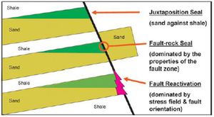
The first order of seal analysis cannot be separated from identifying the juxtaposition of the reservoir in all fracture planes by using layers of interpretation results that have been defined on the fracture plane[5]. It is seen in Figure 3 that in several ways that hydrocarbon fluids can escape. In the top illustration, there is a juxtaposition seal, which means that there is a barrier which is a concern for rocks with low permeability and reservoir. The middle illustration shows that sand to sand juxtaposition which can occur due to the nature of relatively similar permeability. The bottom illustration shows the reactivation of a fault, so that it can become a hydrocarbon migration pathway. Because faults can form porosity which results in the opening of a new fault plane.
[[file:GumelarFigure4.jpg|thumb|300px|4}}Allan Mapping Principles[6]. (a) Fault displacement can provide a cross-fault seal by juxtaposing impermeable units against potential reservoir units. (B) In three dimensions, the interactions of juxtaposed units on the fault surface can be complex. (c) Allan's Mapping technique resolves the fault surface into a flat plane and maps the position of the footwall and hanging-wall. The trap and spill point can then be determined from the alignment of the lithology units.
Allan diagram
Allan[6] developed a graphic technique to map the relative position of the lithology cut-offs on both the footwall and the hanging-wall. This methodology is often called Allan Mapping. Using this approach, cross-fault spill points and hydrocarbon flow path potential can be determined from the lithological alignment (juxtaposition), based on the assumption that the fault itself does not have sealing properties and that it is not an open channel for flow. Allan's mapping relies on the construction of the fault surface section (Figure 4) which is defined as the appearance of the stratigraphic geometry that touches across the fault by removing the hanging-wall[6]. The representation of a part of the fault surface is often a vertical or planar surface. The lithology of the footwall and hanging-wall fault blocks is projected onto the surface portion of the fault and is used to determine where the reservoir lithology of one fault block is juxtaposed with the non-reservoir lithology of the opposite fault block.
See also
References
- ↑ Watts, N. 1987. Theoretical aspects of cap-rock and fault seals for single- and two-phase hydrocarbon columns: Marine and Petroleum Geology, v. 4, p. 274–307.
- ↑ Knipe, R. J., 1992. Faulting processes and fault seal: Structural and tectonic modelling and its application to petroleum geology, Elsevier p. 325-342.
- ↑ Færseth, R. B., 2006. Shale smear along large faults: Continuity of smear and the fault seal capacity: Journal of the Geological Society, v. 163, no. 5, p.741-751.
- ↑ Yielding, G., B. Freeman, and D. T. Needham, 1997, Quantitative fault seal prediction: AAPG Bulletin, v. 81, no. 6, p. 897-917.
- ↑ 5.0 5.1 Yielding, G., P. Bretan, and B. Freeman, 2010, Fault seal calibration: A brief review: Geological Society London Special Publication 347, p. 243-255.
- ↑ 6.0 6.1 6.2 Allan, U. S. 1989, Model for hydrocarbon migration and entrapment within faulted structures: AAPG Bulletin, v. 73, p. 803–811.

