Difference between revisions of "Meandering fluvial reservoirs"
| Line 29: | Line 29: | ||
==Geometry of meander belts== | ==Geometry of meander belts== | ||
Meandering rivers deposit sand and mud within well-defined meander belts. The appearance of a meander belt in plan and cross section is of a complex labyrinth of interlocking sand bodies on the scale of hundreds of meters, embedded within varying volumes of mud ([[:file:M91FG173.JPG|Figure 2]]). The mud can make up 50% or more of the volume. Channel features, where they survive, tend to be plugged with clay ([[:file:M91FG173.JPG|Figure 2]], [[:file:M91FG174.JPG|Figure 3]]). | Meandering rivers deposit sand and mud within well-defined meander belts. The appearance of a meander belt in plan and cross section is of a complex labyrinth of interlocking sand bodies on the scale of hundreds of meters, embedded within varying volumes of mud ([[:file:M91FG173.JPG|Figure 2]]). The mud can make up 50% or more of the volume. Channel features, where they survive, tend to be plugged with clay ([[:file:M91FG173.JPG|Figure 2]], [[:file:M91FG174.JPG|Figure 3]]). | ||
| + | |||
| + | Gibling<ref name=Gibling_2006>Gibling, M. R. 2006, [http://jsedres.geoscienceworld.org/content/76/5/731?related-urls=yes&legid=jsedres;76/5/731 Width and thickness of fluvial channel bodies and valley fills in the geological record: A literature compilation and classification]: Journal of Sedimentary Research, v. 76, p. 731–770.</ref> provided data on width and thickness relationships for fluvial systems in various settings from Quaternary and older outcrops (Table 1). He found that meandering rivers do not generally create thick sedimentary packages. The maximum thickness for meandering river deposits in his database is only 38 m (124 ft), with 4–20 m (13–65 ft) as a common thickness range. Gibling makes the comment that despite their familiarity in the modern landscape, meandering river deposits probably constitute only a minor portion of the fluvial rock record by comparison to braided systems. This may be because the organized flow patterns associated with meandering rivers rarely persist for long periods. | ||
| + | |||
| + | {| class = "wikitable" | ||
| + | |- | ||
| + | |+ {{table number|1}}Width and thickness relationships of fluvial sediments in various settings.<sup>1</sup> | ||
| + | |- | ||
| + | ! Depositional environment || Thickness || Width || Width/thickness ratio | ||
| + | |- | ||
| + | | Braided and low sinuousity rivers || 1-1200 m (3-3937 ft); most < 60 m (197 ft); common range 5-60 m (16-197 ft) || 50 m-1300+ km (164 ft-808+ mi); many > 1 km (0.62 mi); common range 0.5-10 km (0.3-6 mi) || 15-15,000+; some > 1000; common range 50-1000 | ||
| + | |- | ||
| + | | Meandering rivers || 1-38 m (3-125 ft); common range 4-20 m (13-65 ft) || 30 m-15 km (98 ft-9 mi); most < 3 km (1.8 mi); common range 0.3-3 km (0.1-1.8 mi) || 7-940; most < 250; many < 100; common range 30-250 | ||
| + | |- | ||
| + | | Delta distributaries || 1-35 m (3-115 ft); most < 20 m (65 ft); common range 3-20 m (10-65 ft) || 3 m-1 km (10 ft-0.6 mi); most < 500 m (1640 ft); common range 10-300 m (33-984 ft) || 2-245; most < 50; many < 15; common range 5-30 | ||
| + | |- | ||
| + | | Channels in eolian settings || 1-19 m (3-62 ft) || 2.5-1500 m (8.2-4921 ft); most < 150 m (492 ft) || 1-90; most < 15 | ||
| + | |- | ||
| + | | Valley fills on bedrock unconformities || 12-1400 m (39-4593 ft); most < 500 m (1640 ft) || 75 m-52 km (246 ft-32 mi); most < 10 km (6 mi) || 2-870; highly variable; mainly 2-100 | ||
| + | |- | ||
| + | | Valley fills within alluvial and marine strata || 2-210 m (6-689 ft); most < 60 m (197 ft) || 0.1-105 km (0.06-65 mi); common range 0.2-25 km (0.1-15 mi) || 4.6-3640; highly variable; common range 10-1000; many from 100 to 1000 | ||
| + | |- | ||
| + | | colspan="4" | <sup>1</sup>''From Gibling<ref name=Gibling_2006 />, Journal of Sedimentary Research. Reprinted with permission from, and © by, the SEPM (Society for Sedimentary Geologists).'' | ||
| + | |} | ||
| + | |||
Revision as of 18:16, 31 July 2015
This page is under construction
| Oil Field Production Geology | |

| |
| Series | Memoirs |
|---|---|
| Part | The Production Geologist and the Reservoir |
| Chapter | Eolian reservoirs |
| Author | Mike Shepherd |
| Link | Web page |
| PDF file (requires access) | |
| Store | AAPG Store |
Fluvial reservoirs are difficult for the production geologist to understand, characterize, and model. One major problem involves trying to classify fluvial reservoirs in the subsurface. The system used in this book broadly categorizes fluvial systems into meandering and braided fluvial reservoirs. Although this is a classification used by many production geologists, not all experts are happy with this approach; some believe the classification to be too prescriptive. They consider that only limited inferences can be made from core and log data as to the overall geometry of a fluvial reservoir in the subsurface (e.g., Bridge[1]). Because of this, some geologists prefer to use a simple nongeneric description by classifying subsurface fluvial geometries as either sheets or ribbons.[2]

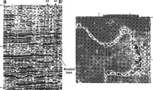
Despite the above difficulties, the production geologist will nevertheless try and find some basis for providing a predictive model for the subsurface geology of a fluvial reservoir. Seismic data can help to determine the planform geometry where it is of sufficient resolution (Figure 1). Fluvial geometries can sometimes be well differentiated on horizon slice amplitude displays (e.g., Brown et al.,[4] Rijks and Jauffred,[5] Noah et al.,[6] Carter[7]).
Meander belt reservoirs show different production behavior characteristics from braided river reservoirs; in the absence of seismic geomorphology evidence, the production geologist should intuitively pick the fluvial geometry type most likely to fit the available data and the reservoir performance. Perhaps because of the uncertainty involved in determining the planform geometry in fluvial reservoirs, the scenario approach (see Reservoir uncertainty) may be an appropriate tool to help evaluate fluvial reservoirs.


Geometry of meander belts
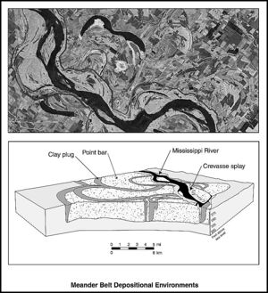
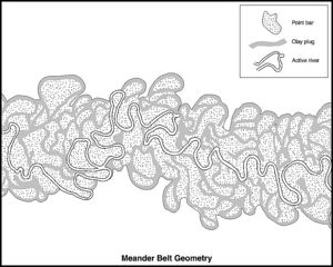
Meandering rivers deposit sand and mud within well-defined meander belts. The appearance of a meander belt in plan and cross section is of a complex labyrinth of interlocking sand bodies on the scale of hundreds of meters, embedded within varying volumes of mud (Figure 2). The mud can make up 50% or more of the volume. Channel features, where they survive, tend to be plugged with clay (Figure 2, Figure 3).
Gibling[10] provided data on width and thickness relationships for fluvial systems in various settings from Quaternary and older outcrops (Table 1). He found that meandering rivers do not generally create thick sedimentary packages. The maximum thickness for meandering river deposits in his database is only 38 m (124 ft), with 4–20 m (13–65 ft) as a common thickness range. Gibling makes the comment that despite their familiarity in the modern landscape, meandering river deposits probably constitute only a minor portion of the fluvial rock record by comparison to braided systems. This may be because the organized flow patterns associated with meandering rivers rarely persist for long periods.
| Depositional environment | Thickness | Width | Width/thickness ratio |
|---|---|---|---|
| Braided and low sinuousity rivers | 1-1200 m (3-3937 ft); most < 60 m (197 ft); common range 5-60 m (16-197 ft) | 50 m-1300+ km (164 ft-808+ mi); many > 1 km (0.62 mi); common range 0.5-10 km (0.3-6 mi) | 15-15,000+; some > 1000; common range 50-1000 |
| Meandering rivers | 1-38 m (3-125 ft); common range 4-20 m (13-65 ft) | 30 m-15 km (98 ft-9 mi); most < 3 km (1.8 mi); common range 0.3-3 km (0.1-1.8 mi) | 7-940; most < 250; many < 100; common range 30-250 |
| Delta distributaries | 1-35 m (3-115 ft); most < 20 m (65 ft); common range 3-20 m (10-65 ft) | 3 m-1 km (10 ft-0.6 mi); most < 500 m (1640 ft); common range 10-300 m (33-984 ft) | 2-245; most < 50; many < 15; common range 5-30 |
| Channels in eolian settings | 1-19 m (3-62 ft) | 2.5-1500 m (8.2-4921 ft); most < 150 m (492 ft) | 1-90; most < 15 |
| Valley fills on bedrock unconformities | 12-1400 m (39-4593 ft); most < 500 m (1640 ft) | 75 m-52 km (246 ft-32 mi); most < 10 km (6 mi) | 2-870; highly variable; mainly 2-100 |
| Valley fills within alluvial and marine strata | 2-210 m (6-689 ft); most < 60 m (197 ft) | 0.1-105 km (0.06-65 mi); common range 0.2-25 km (0.1-15 mi) | 4.6-3640; highly variable; common range 10-1000; many from 100 to 1000 |
| 1From Gibling[10], Journal of Sedimentary Research. Reprinted with permission from, and © by, the SEPM (Society for Sedimentary Geologists). | |||
See also
- Eolian reservoirs
- Braided fluvial reservoirs
- Deltaic reservoirs
- Deep-water marine reservoirs
- Carbonate reservoirs
References
- ↑ Bridge, J. S., 2003, Rivers and flood plains: Forms, processes and sedimentary record: Oxford, Blackwell, 491 p.
- ↑ Friend, P. F., M. J. Slater, and R. C. Williams, 1979, Vertical and lateral building of river sandstone bodies, Ebro Basin, Spain: Journal of the Geological Society of London, v. 136, p. 39–46.
- ↑ Burnett, M., 1996, 3-D seismic expression of a shallow fluvial system in west central Texas, in P. Weimer and T. L. Davis, eds.: AAPG Studies in Geology 42 and SEG (Society of Exploration Geophysicists) Geophysical Developments Series 5, p. 45–56.
- ↑ Brown, A. R., C. G. Dahm, and R. J. Graebner, 1981, A stratigraphic case history using three-dimensional seismic data in the Gulf of Thailand: Geophysical Prospecting, v. 29, no. 3, p. 327–349.
- ↑ Rijks, E. J. K., and J. C. E. M. Jauffred, 1991, Attribute extraction: An important application in any detailed 3D interpretation study: Leading Edge, v. 10, no. 9, p. 11–19.
- ↑ Noah, J. T., G. S. Hofland, and K. Lemke, 1992, Seismic interpretation of meander channel point-bar deposits using realistic seismic modeling techniques: The Leading Edge, v. 11, p. 13–18.
- ↑ Carter, D. C., 2003, 3-D seismic geomorphology: Insights into fluvial reservoir deposition and performance, Widuri field, Java Sea: AAPG Bulletin, v. 87, no. 6, p. 909–934.
- ↑ Jordan, D. W., and W. A. Pryor, 1992, Hierarchical levels of heterogeneity in a Mississippi river meander belt and application to reservoir systems: AAPG Bulletin, v. 76, no. 10, p. 1601–1624.
- ↑ Sun, T., P. Meakin, T. Jossang, and K. Schwarz, 1996, A simulation model of meandering rivers: Water Resources Research, v. 32, pt. 9, p. 2937–2954.
- ↑ 10.0 10.1 Gibling, M. R. 2006, Width and thickness of fluvial channel bodies and valley fills in the geological record: A literature compilation and classification: Journal of Sedimentary Research, v. 76, p. 731–770.