Deep-water marine reservoirs
| Oil Field Production Geology | |

| |
| Series | Memoirs |
|---|---|
| Part | Depositional Environments and their Flow Characteristics |
| Chapter | Deep-water Marine Reservoirs |
| Author | Mike Shepherd |
| Link | Web page |
| PDF file (requires access) | |
| Store | AAPG Store |
Deep-water marine reservoirs have been increasingly found since the 1970s, particularly as a result of an increase in offshore drilling activity. Many of these are Tertiary in age, although large reservoirs of Jurassic and Cretaceous age have also been found, particularly in the North Sea.
The term deep water has been used in two different ways. It applies in a geological context to deep-water systems that have been transported by gravity flow processes in a marine setting.[1] Deep water is also defined as present-day sea depths in excess of 500 m (1640 ft) deep.
Since 1984 there has been an intensive effort in exploring for reservoirs located in present-day deep water with numerous prolific discoveries.[2] Deep-water exploration in the Gulf of Mexico, Brazil, and west Africa is targeting and finding a large number of hydrocarbon pools in deep-water marine-sand systems. Only about 20% of these reservoirs had been developed to 2004.[1]
Deep-water marine reservoirs can be prolific reservoirs
Deep-water marine sandstones can be prolific reservoirs where they occur. They commonly contain oil fields as a result of the interfingering of gravity-flow sandstones with marine oil-prone source rocks. An example is the interfingering of the Upper Jurassic submarine fans of the UK North Sea with the Kimmeridge Clay Formation source rock for the province, e.g., the Magnus and Claymore fields.[3][4]
The reservoir quality of deep-marine sandstones is among the best of the various sedimentary environments that comprise reservoirs. Porosities, permeabilities, and net-to-gross ratios are typically high. Under favorable conditions, deep-water sandstones may be ponded and stacked vertically into very thick, sand-rich intervals (Table 1). These reservoirs are very profitable as they can be produced by a small number of wells at very high rates.[1]
| Characteristic | Favorable for Reservoir Development | Unfavorable for Reservoir Development |
|---|---|---|
| Under favorable conditions, deep-water marine sandstones can form very thick, high net-to-gross reservoirs | Produce at high rates with high ultimate recovery; can provide reservoirs for very profitable fields | |
| Depositionally isolated channel-fill sandstones in channelized systems | Create compartmentalized reservoirs requiring a multiwell development scheme | |
| Widespread amalgamation of channel-fill sandstones in channelized systems | Creates laterally and vertically connected high-volume reservoirs | |
| Shale drapes or late-stage channel-fill shales common in channel-fill sandstones | Reduces vertical and lateral connectivity between individual channel-fill sandstones | |
| Preferential water ingress along channel axes | Banked oil may form along channel margins | |
| Levee sediments are commonly in poor communication with the channel-fill sandstones in channel-levee complexes | Bypassed oil in levee sediments | |
| Levee sediments in channel-levee complexes are thin bedded but can show reservoir connectivity across a large area | Levee sediments can be a production target in their own right | |
| Laterally extensive mudstones commonly form permeability barriers to vertical flow | Encourages edge-water drive and can suppress early water production | Creates hydraulic units; water overrun is common |
| Fill and spill geometries | Potential to create bypassed oil volumes in cellar oil accumulations |
Typical settings for deep-water marine reservoirs
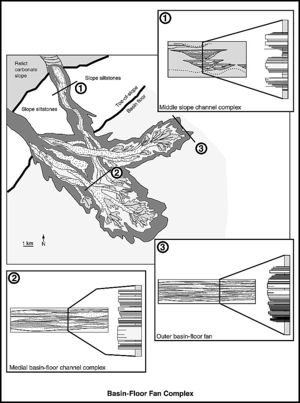
The main settings include
- channelized systems;
- channel-levee complexes; and
- sheet complexes (including lobes).
Other settings include mass transport complexes, which are generally too heterogenous to form major reservoir intervals, and remobilized sandstone reservoirs. The latter are reservoirs that have undergone significant postdepositional mobilization with the formation of deformed sand pods, dykes, and sills (injectites). They are common in the Tertiary of the North Sea (e.g., Hurst and Cartwright[6]).
Problems in characterizing deep-water marine sandstones
Deep-water marine sandstone systems can be difficult to characterize in the subsurface. The basic problem is in trying to differentiate sheet sandstones from channel complexes. Sheet sandstones are typically well connected laterally and can be very productive. By contrast, the large-scale reservoir connectivity of channel complexes can vary between good, where they have coalesced into connected bodies, and none at all, where they are depositionally isolated. Channel complex connectivity will depend upon whether the individual channels show extensive sand-sand contacts with each other or not. It is not always easy to assess this with limited well control. This is a particular problem when it comes to the costly appraisal of deep-marine sandstone reservoirs offshore.[7]
Weimer and Slatt[1] gave guidelines on how to differentiate between sheet and channelized deep-marine sandstones. If the log patterns and net-to-gross ratios vary considerably over short distances between wells, then the chances are that this is a channelized system.[8] A typical pattern is for channels to have high net-to-gross values and a blocky log response in the channel axis, with lower net-to-gross values and a serrated log response toward the margins (Figure 1). In core, channel-fill sandstones can show erosional features such as erosional bases, shale clasts, and an abundance of chaotic looking sediments.
Sheet sandstones and their associated shale interbeds are more layered and massive both at the core and interwell scale. Erosive features are relatively rare with few or no shale rip-up clasts. Post-production formation tester data can help to recognize the high degree of lateral continuity likely to be present here.
Production from channelized systems
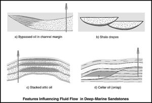
The channel axes may act as pathways for the preferential ingress of water. This can result in the stranding of banked oil along the channel margin pinch-out edges (Figure 2a).[9]
Channel fills can show differing degrees of amalgamation laterally and vertically (Figure 1). The degree of sandstone continuity is influenced by the stacking patterns. In channelized systems, this can be a critical parameter in assessing economic feasibility for reservoir appraisal, e.g., as in the appraisal of the Schiehallion field, offshore United Kingdom (see Chapter 3, this publication).[10] Eubanks[11] described channelized turbidites from the Oligocene lower Hackberry sands of the North Sabine Lake field, Louisiana. Stacking of individual channels resulted in a large amalgamated reservoir interval with pressure communication throughout. Isolated channels also occur, but these have shown rapid depletion within 2 months following production start-up.
Connectivity between individual channels will depend on how much shale is present. The effect of increasing shale content is to reduce vertical connectivity through sand-on-sand contacts and also to increase lateral variability.[1]
Shales may be present either as extensive late-stage channel-fill shales or as shale drapes at the base of the channels. They may be composed of mudstone, siltstone, or heterolithic sediments (Figure 2b).[5] Simulation modeling indicates that shale drapes may be a significant feature reducing connectivity between channel complexes and impairing the recovery efficiency.[12] This mechanism has been invoked to explain why channel margins in the Forties field, UK North Sea, appear to act as baffles to fluid flow.[13]
According to Weimer and Slatt,[1] the width to thickness ratio of channels typically ranges from 10:1 to 300:1.
Production from channel-levee complexes
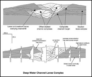
Channel-levee complexes can show highly variable continuity between the channels and levees (Figure 3). It is common for hydrocarbons in the channel-fill sandstones to be poorly connected with the levee sediments. The channel fills may be younger than the levees themselves, and the beds in the proximal levee deposits may be discontinuous.[15][14] Kneller et al.[16] noted that collapse structures, including rotated blocks, slide sheets, slump folds, and thick debris flows, are common on levee margins and may contribute to poor reservoir continuity.
Injection wells located in overbank splays have poor communication with wells in the channel fill of the East Ford field in Texas.[17] The levee deposits can be a production target in their own right. In the Ram-Powell field in the Gulf of Mexico, production data indicate that levee deposits, although thin bedded, can show reservoir connectivity over a large area and give impressive production rates.[18][1]
Production from sheet complexes
Sheet sandstones form excellent reservoirs. Their characteristics include simple tabular geometries, good lateral continuity, and few erosional features.[1] A large volume of deep-water sheet sandstones can be produced by a single production well. Width-to-thickness ratios are large, more than 500:1 for sheet complexes compared to a range of 10:1 to 300:1 for channels.[1] Vertical connectivity can be variable depending on the amount of interbedded shales or the degree of sand-on-sand amalgamation.
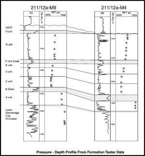
Thin but laterally extensive mud blankets, either deposited from hemipelagic settling or the muddy tails of turbidity flows, can form permeability barriers to vertical flow in these systems (e.g., Hempton et al).[20] Shales representing maximum flooding surfaces are commonly permeability barriers. Large-scale debris flows also have the potential to form baffles and barriers. Shales can subdivide the reservoir into several hydraulic units.[21] In certain favorable circumstances, these blanket shales can lead to a more efficient recovery by encouraging edge-water drive and suppressing bottom-water influx into the basal perforations of production wells. This type of flow behavior can be recognized on the basis of formation tester pressure discontinuities (Figure 4) and slow-rising oil-water contacts on pulsed neutron logs. A typical management strategy in deep-water reservoirs with extensive shales is to isolate water-producing perforations in production wells by setting a plug in the well opposite one of these shale barriers.
Water overrun above laterally extensive shales is a common feature in sheet complexes. Stranded oil can be found under these shales. Blanket shales also have the potential to form multiple attic oil targets under local structural culminations in deep-water sediments (Figure 2c).
Cellar oil targets can also occur (Figure 2d). Early sand input into a receiving basin tends to pond into the bathymetric lows. The seabed will eventually become smoother as the lows are filled in. Later sand flows will spill beyond the extent of the previous flows. These show a more tabular geometry and will be spread across a larger area than the underlying sediments, creating a fill and spill geometry. The ponded sand bodies can potentially hold isolated oil volumes by comparison to the more extensive later flows, which may be better swept.
See also
- Eolian reservoirs
- Braided fluvial reservoirs
- Deltaic reservoirs
- Siliciclastic shorelines and barrier island reservoirs
- Meandering fluvial reservoirs
- Carbonate reservoir
References
- ↑ 1.0 1.1 1.2 1.3 1.4 1.5 1.6 1.7 1.8 Weimer, P., and R. M. Slatt, 2004, Petroleum systems of deep-water settings: SEG/EAGE (Society of Exploration Geophysicists/European Association of Geoscientists and Engineers) Distinguished Instructor Series 7, 465 p.
- ↑ Pettingill, H. S., and P. Weimer, 2001, Global deep-water exploration: Past, present and future frontiers, in R. H. Fillon, N. C. Rosen, P. Weimer, A. Lowrie, H. W. Pettingill, R. L. Phair, H. H. Roberts, and B. Van Hoorn, eds., Petroleum systems of deep-water basins: Global and Gulf of Mexico experience: GCS-SEPM Foundation, p. 1–22.
- ↑ Shepherd, M., C. J. Kearney, and J. H. Milne, 1990, Magnus field, in E. A. Beaumont and N. H. Foster, eds., Structural traps: II. Traps associated with tectonic faulting: Treatise of petroleum geology of oil and gas fields: Tulsa, AAPG, p. 95–125.
- ↑ Harker, S. D., S. C. H. Green, and R. S. Romani, 1991, The Claymore field, Block 14/19, UK North Sea, in I. L. Abbots, ed., United Kingdom oil and gas fields, 25 years commemorative volume: Geological Society (London) Memoir 14, p. 269–278.
- ↑ 5.0 5.1 Beaubouef, R. T., C. Rossen, F. B. Zelt, M. D. Sullivan, D. C. Mohrig, and G. D. C. Jennette, 1999, Field guide for AAPG Hedberg field Research Conference, April 15–20, 1999, Deep-water sandstones, Brushy Canyon Formation, west Texas: AAPG Continuing Education Course Note Series 40, 48 p.
- ↑ Hurst, A., and J. Cartwright, 2007, Relevance of sand injectites to hydrocarbon exploration and production, in A. Hurst and J. Cartwright, eds., Sand injectites: Implications for hydrocarbon exploration and production: AAPG Memoir 87, p. 1–19.
- ↑ Steffens, G. S., R. C. Shipp, B. E. Prather, A. Nott, J. L. Gibson, and C. D. Winker, 2004, The use of near-sea floor 3D seismic data in deep-water exploration and production, in R. J. Davies, J. A. Cartwright, S. A. Stewart, S. A. Lappin, and J. R. Underhill, eds., 3D seismic technology, applications to the exploration of sedimentary basins: Geological Society (London) Memoir 29, p. 35–43.
- ↑ Chapin, M. A., P. Davies, J. L. Gibson, and H. S. Pettingill, 1994, Reservoir architecture of turbidite sheet sandstones in laterally extensive outcrops, Ross Formation, western Ireland, in P. Weimer, A. H. Bouma, and B. F. Perkins, eds., Submarine fans and turbidite systems: Gulf Coast Section SEPM Foundation 15th Annual Research Conference, v. 15, p. 53–68.
- ↑ Clark, M. S., J. D. Melvin, R. K. Prather, and A. W. Marino, 1997, Characterization and exploitation of the distal margin of a layered, low-permeability turbidite reservoir, Yowlumne field, San Joaquin Basin, California: Houston Geological Society Bulletin, v. 40, no. 4, p. 12–15.
- ↑ Leach, H. M., N. Herbert, A. Los, and R. L. Smith, 1999, The Schiehallion development in A. J. Fleet and S. A. R. Boldy, eds., Petroleum geology of northwest Europe: Proceedings of the 5th Conference, Geological Society (London), p. 683–692.
- ↑ Eubanks, L. G., 1987, North Sabine Lake field: Complex deposition and reservoir morphology of lower Hackberry (Oligocene), southwest Louisiana: AAPG Bulletin, v. 71, no. 10, p. 1162–1170.
- ↑ Larue, D. K., 2004, Outcrop and waterflood simulation modeling of the 100-foot channel complex, Texas, and the Ainsa II channel complex, Spain: Analogs to multistory and multilateral channelized slope reservoirs, in G. M. Grammer, P. M. Harris, and G. P. Eberli, eds., Integration of outcrop and modern analogs in reservoir modeling, AAPG Memoir 80, p. 337–364.
- ↑ Vaughan, O., R. Jones, and S. Plahn, 2007, Reservoir management aspects of the rejuvenation of the Forties field, UKCS: Presented at Offshore Europe, Society of Petroleum Engineers, September 4–7, 2007, Aberdeen, SPE Paper 109012, 20 p.
- ↑ 14.0 14.1 Beaubouef, R. T., 2004, Deep-water leveed channel complexes of the Cerro Toro formation, Upper Cretaceous, southern Chile: AAPG Bulletin, v. 11, p. 1471–1500.
- ↑ Cronin, B. T., A. Hurst, H. Celik, and I. Turkmen, 2000, Superb exposures of a channel, levee and overbank complex in an ancient, deep-water slope environment: Sedimentary Geology, v. 132, p. 205–216.
- ↑ Kneller, B., M. Dykstra, and P. Thompson, 2007, Collapse of submarine channel levees, examples from outcrop and subsurface, and reservoir implications: Abstracts of the 2007 AAPG Annual Convention and Exhibition, p. 77.
- ↑ Dutton, S. P., W. A. Flanders, and M. D. Barton, 2003, Reservoir characterization of a Permian deep-water sandstone, East Ford field, Delaware basin, Texas: AAPG Bulletin, v. 87, no. 4, p. 609–627.
- ↑ Shew, R. D., G. M. Tiller, C. J. Hackbarth, D. R. Rollins, and C. D. White, 1995, Characterization and modeling of channel and thin-bedded turbidite prospects in the Gulf of Mexico: Integration of outcrops, modern analogs, and subsurface data: Presented at the Society of Petroleum Engineers Annual Technical Conference and Exhibition, October 22–25, 1995, Dallas, Texas, SPE Paper 30535, 7 p.
- ↑ Morris, P. H., S. N. J. Payne, and D. P. J. Richards, 1999, Micropalaeontological biostratigraphy of the Magnus Sandstone Member (Kimmeridgian to early Volgian), Magnus field, UK North Sea, in R. W. Jones and M. D. Simmons, eds., Biostratigraphy in production and development geology: Geological Society (London) Special Publication 152, p. 55–73.
- ↑ Hempton, M., J. Marshall, S. Sadler, N. Hogg, R. Charles, and C. Harvey, 2005, Turbidite reservoirs of the Sele Formation, central North Sea: Geological challenges for improving production, in A. G. Dore and B. A. Vining, eds., Petroleum geology: Northwest Europe and global perspectives: Proceedings of the 6th Petroleum Geology Conference, Geological Society (London), v. 1, p. 449–459.
- ↑ Lowry, P., C. D. Jenkins, and D. J. Phelps, 1993, Reservoir scale sand body architecture of Pliocene turbidite sequences, Long Beach Unit, Wilmington oil field, California: Presented at the Society of Petroleum Engineers Annual Technical Conference and Exhibition, October 3–6, Houston, Texas, SPE Paper 26440, 10 p.
