Coal bed methane (UDip)
| Wiki Write-Off Entry | |
|---|---|

| |
| Student Chapter | Universitas Diponegoro |
| Competition | June 2015 |
Coal bed methane (CBM) is one of the unconventional energy sources which many countries have been started to be explored seriously and coal bed methane is kind of renewable energy. CBM is notably different from a typical conventional gas reservoir, as the methane is stored within the coal by a process called adsorption. The methane is in a near-liquid state, and lines the inside of pores within the coal (called the matrix). The open fractures in the coal (called the cleats) can also contain free gas or can be saturated with water. The system is then called a “dual-porosity reservoir”, one characterized by a complex interaction of the coal matrix and cleat system coupled through the desorption process. The mechanism for gas flow in the coal involves three steps:
- desorption of the gas from the coal surface inside the micropores,
- diffusion of the gas through the micropores of the coal matrix, and
- Darcy flow through the fracture (cleat) network to the wellbore.
Therefore research of CBM is important.
For many years, the western frontier of CBM development seemed to have progressed no farther than the Uinta Basin. Coals found near the surface were mined beginning in the 1850s and the underground workings reveal much of what geologist know about the intricate structure and the nature of the coals themselves, including the presence of gas. Indeed, it was the documentation of methane-related mine incidents and the famous “Flaming Geyser” phenomenon at a 1911 well site in King County that first attracted Amoco and a number of independents to explore for CBM gas in western Washington in the 1980s[1]
The porosity and permeability of coal
Porosity
Porosity (φ) is one of the physical characteristic of CBM reservoir. Porosity material is defined as the fraction of the bulk volume of material that is not occupied by the solid framework of the material. In CBM reservoirs, the porosity represents the percentage of the total space that is available to fill by liquids or gases. There are two main types of porosity absolute porosity and effective porosity. Effective porosity is percentage of interconnected void space with respect to the bulk volume. Effective porosity indicates value of conductivity fluid in formation. Absolute porosity is the percentage of total void space with respect to the bulk volume regardless of the interconnection of the pore voids. A rock may have considerable absolute porosity and yet have no conductivity to fluid for lack of pore interconnection.
Permeability
Permeability (k) is a property of the porous medium and is a measure of the capacity of the medium to transmit fluids. The measurement of permeability, then, is a measure of the fluid conductivity of the particular material. The principle of measurement of fluid in a porous medium by Henry Darcy in 1856 is comparable to the pressure difference per unit length. This relationship was derived from data obtained from several experiments on the vertical flow of water through the gravel
![{\displaystyle k={\frac {2000P_{in}\mu Q_{a}L}{A[P_{in}(P_{in}-P_{out})P_{out}]}}}](https://wikimedia.org/api/rest_v1/media/math/render/svg/e86a353766f08e0d5e060e79eb01b93511efbb4a)
Where
- k = permeability of the medium, milidarcys
- μ = viscosity of the fluid, centipoises
- Q = flow rate, cc/sec
- L = core length, cm
- A = core cross-sectional area, cm2
- Pin = pressure in, atm
- Pout = pressure out, atm
One darcy permeability is defined as the passing fluid with a viscocity centipoises with a flow rate 1 cc/sec through a cross-sectional area of 1 cm2 with a reduced pressure of 1 atm/cm. There are three methods to measure the porosity of coal: thin slice, scanning electron microscopy (SEM), and digital helium porosity.
Methods used to determine the characterization of coal as CBM reservoir, porosity and permeability

There are three main methods to determining the characterization of coal.
First, porosity measurement by means of helium porosity meter. This tool uses helium gas as a pore filler samples. Data obtained from the use of this tool is the data in the form of pressure and volume of helium gas that fills the pores of the sample. Boyle Law’s used for calculating porosity. The equation which used for that data is:


Where
- P1 = input pressure (atm)
- V1 = volume of tube (cm3)
- P2 = output pressure (atm)
- V2 = bulk volume (cm3)
Second, porosity estimation from thin slice images through digital image processing. Thin slice is a method used to slice thin cross-sectional view of the coal samples. Thin slice preparation was glued to the glass. Cross sections were observed using a microscope. Observations, as seen from the microscope shown in Figure 1.
Third, helium permeability measurement and imaging coal sample using SEM (Scanning Electron Microscope). SEM (Scanning Electron Microscope) is a type of electron microscope that images a sample by scanning it with a beam of electrons in a raster scan pattern. Magnification that we used are 400 times, 3000 times, 35.000 times, and 70.000 times. At 400 times magnification, we can see the pore and the fracture in coal sample (Figure 2). If we increase magnification until 3000 times, we see the fracture clearly (Figure3). But, if we do more magnification (more than 3000 times), at fracture location, the image not clearly to see. The fracture can be seen until 35.000 times of magnification (Figure 4). Moreover, the fracture can not be seen clearly at 70.000 times of magnification (Figure 5).
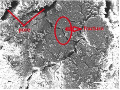
Figure 2 The cross sections of coal using SEM at magnification 400 times
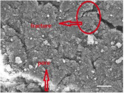
Figure 3 The cross sections of coal using SEM at magnification 3000 times
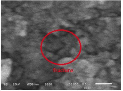
Figure 4 The cross sections of coal using SEM at magnification 35000 times
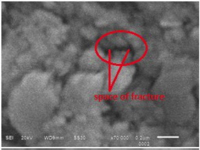
Figure 5 The cross sections of coal using SEM at magnification 70000 times


Results of the methods
Picture taken in the program minisee (Figure 1) is processed using Img2por_v003 program. From that program, we calculated the porosity:

From Figure 6, the red one shows pore of coal and the blue one shows matrix of coal. The information that we get from Figure 6 is the porosity of coal samples with that program is 24.8%. In the other hand, porosity measurement by method of helium porosity meter which is based on ideal gas law obtained the porosity of coal is 24.4%. It means the maximum probability gas contained in coal equal 24.4–24.8%. Porosity of the resulting value is the value of total porosity (absolute porosity and effective porosity). In addition, the amount of porosity is used to determine the amount of fluids (oil and water) and gas. Permeability values obtained from the test is equal to 40.43 mD. Permeability value shows that a flow of 40.43 milli cc, fluid (gas), moves through porous and fracture. The low of permeability indicated that there is another porosity from fracture as secondary porosity. So, based on our experiment we found that the high porosity result and the low permeability result indicate that this coal dominated by absolute porosity.
From the results of the study concluded that the coal samples had a unique porosity characteristic. This can be seen from the value of 24.8% porosity and permeability values of 40.43 mD. A small value of permeability indicates that it comes from the secondary porosity. As we know, the secondary of porosity comes from fracture. Apart from testing the porosity and permeability test, the uniqueness of the coal samples also can be seen from the SEM test with 400 times, 3000 times, 35,000 times, and 70,000 times magnifications. In addition, the uniqueness can also be on Figure 2, Figure 3, Figure 4, and Figure 5. To sum up, the characteristics of sample coal shows that it is good as a CBM reservoir.
References
- ↑ Schwochow, S. D., 2006, Coalbed gas plays, west and east—A study in contrasts: An investor’s guide to coalbed methane, A supplement to Oil and Gas Investor, v. 26, no. 12, p. 2-7.
Other sources
- Amyx, J., M. D. Bass, and L. R. Whiting, 1960, Petroleum Reservoir Engineering: New York, McGraw-Hill.
- Bass, D. M., Jr., 1987, Properties of reservoir rocks, in H. Bradley, ed., Petroleum Engineering Handbook: Houston, Texas, Society of Petroleum Engineers.
- Guèguen, Y., and V. Palciauskas, 1994, Introduction to the physics of rocks: Princeton, New Jersey, Princeton University Press, 297 p.
- Heinemann, Z. E., 2005, Fluid flow in porous media Volume 1.Leoben. 6 – 12
- Nelson, R. A., 2001, Geologic analysis of Naturally fractured reservoirs: Elsevier, 352 p.
- Pirson, S. J., 1958, Oil reservoir engineering: New York, McGraw-Hill, 735 p.
- Ursin, J., and A. B. Zolotukhin, 1997, Introduction to reservoir engineering: Høyskoleforlaget, Norway, Norwegian Academic Press, 407 p.