Introduction to biosteering operation
| Wiki Write-Off Entry | |
|---|---|

| |
| Author | Thamer Alnasser and Fahad Badqaish |
| Affiliation | Saudi Aramco |
| Competition | 2021 Middle East Wiki Write Off |
The use of seismic interpretation is a critical element in modelling the subsurface geology. Exploration drilling plans are made primarily based on seismic results in addition to offset well data. Plans include primary targets, coring points, casing depths, overpressure zones and planned terminal depth. While drilling, discrepancies from prognosis are likely to be found. Logging while drilling (LWD) tools and lithologic description are used to make the necessary adjustments while drilling to optimize drilling costs and reduce drilling risks.
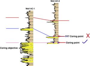
Biostratigraphic studies contribute in making critical decisions while drilling by tying the actual stratigraphy drilled with prognosed. A paleontologist can be deployed to rig site and offers real time biostratigraphic support through continuous analysis of cuttings. A biostratigrapher provides information related to age determination, paleoenvironment deposition and presence of unconformities or faults in the drilling section.
The commonly employed microfossil groups in wellsite biostratigraphy are foraminifera, palynomorphs and nannofossils. Each group require different sample preparation and processing techniques. The interpretation of these individual groups can be utilized to solve specific geological paleoenvironment and stratigraphic problems. In each of these groups, “index fossils” (a term used to define distinctive, abundant, short lived species) are the main microfossils identified to provide age information and stratigraphic position. Using index fossils, it is possible to divide the subsurface into a series of biozones that are very helpful for well correlation and recognizing repeating or missing sections.
Integrating biostratigraphic analysis with seismic data, LWD measurements and lithologic description offers an invaluable framework to field studies i.e. well correlations, sequence stratigraphy and reservoir characterization. By understanding the geologic sequence stratigraphic framework and the applications of biostratigraphy, biosteering options can be explored. Biosteering is envisioned to maximize reservoir contact through horizontal drilling.
Introduction[edit]
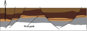
Biosteering is a biostratigraphic application that is intended to offer real time monitoring of horizontal drilling through reservoir layers. It was first applied in 1987 by Maersk Olie and Gas AS on the Dan Field in the North Sea.[2] Several case studies are published to highlight how biosteering is used in development projects, including Andrew and Valhall fields in the North Sea targeting subsequently deep marine clastics in the late Paleocene and deep marine carbonates in the Late Cretaceous.[3] See also Holmes,[4] and Yang-Logan et al.,[5] for other examples.
Over the years, biosteering techniques have evolved, to the point where they became essential in well placement, planning deviated and horizontal well trajectories and can be used in field deposition modelling. The success of biosteering around the world led to the introduction of the application in the Middle East. For over a decade, biosteering has been performed in Qatar, United Arab Emirates, Saudi Arabia, Oman and other countries (see Ship and Marshall, [6] Marshall et al.,[7] Henderson and Marshall,[8] and Hughes et al.[9]).
Biosteering in the Middle East has been applied successfully in Underbalanced Coiled Tubing Drilling (UBCTD). After years of field production and the subsequent depletion of reservoir pressure, UBCTD has been used to improve production with the following benefits (see Ladmia et al.,[10] Hughes et al.,[9] and Matanovi et al.[11]):
- Ability to access low pressure reservoirs and prevention of differential sticking
- The use of angular motors that offers high drilling angles for a quick directional response
- Uses water as drilling fluid, decreasing circulation time allowing more samples to be analyzed
- Faster drilling and eliminating the use of expensive fluids
- Enhanced reservoir performance through increased productivity and reduced formation damage
The use of biosteering in UBCTD compensates for the lack of LWD tools due to the narrow nature of the coil tube. Information available is restricted to simple drilling parameters, Rate of penetration (ROP), Weight on bit (WOB), Near-bit inclination (NBI), Gamma Ray (GR) and few other parameters. The sonde GR instrument is often placed 30 – 40 ft behind the drilling bit. Hence, biosteerers rely heavily on recovery of cuttings in enough quantity to be able to analyze the biocomponents and determine the bit position.
Biosteering is a cuttings based technique relying on the microfossil analyses of samples to determine relative stratigraphic position. These results are relayed in real time to the directional driller and decisions are made as to the trajectory of the bit. Depending on the drilling speed, results from analyses can be provided before the GR response depending on drilling speed.
Techniques of plotting the well trajectory and communicating the relevant directional angle to the directional driller have evolved over the years. These days, there are specific software used to plot well trajectory and provide rapid response to the drillers once the samples are analyzed for optimized reservoir contact.
Planning[edit]
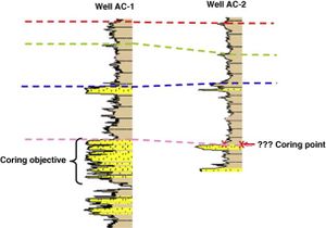
The success of biosteering is dependent on a high resolution biostratigraphic scheme established prior to the development plan. This is accomplished through detailed closely spaced, biostratigraphic analysis of offset wells drilled throughout the field, either by analyzing cores or through cuttings when cores are absent. The biostratigraphic scheme is used to establish local biozones or units that separate the reservoir from the confining layers based on the fossil content.[12] A biostratigraphic scheme is constructed based on the following workflow:
- Examining which microfossil group is useful for the development project
- Analyzing the microfossil assemblages of needed groups in detail
- Interpreting biozonation types from the analyzed microfossils
- Constructing the scheme and testing a pilot study
| C3 | C3-1 | Packstone-Ooid Grainstone | A | Packyphloia | B | Globivalvulina & Permocalculus | C | Poor Assemblage, dolomitized packstone | |
|---|---|---|---|---|---|---|---|---|---|
| C3-2 | Packstone Nodosinelloides | A | Brachiopod-Gastropod | B | Hemigordius-Mitzia-Brunsiella | C | Bryozoa | D | Frondina |
| C4 | C4-1 | Paraglobovalvulina Ooid-coated grain | A | Bivalve | B | Midiella=Agathammina | C | Nodosinelloides | |
| C4-2 | Poor assemblage highly dolomitized | ||||||||
| C4-3 | Peloid packstone Permocalculus | A | Protonodosaria-Nodosaria | B | Barren | C | Paradagmarita-Frondina | ||
| C5 | C5-1 | Wackestone-Agathammina & Echinoid | |||||||
| C5-2 | Microcrystalline Dolomite | A | AeolisaccuNodosaria | B | Gymnocodium | C | Ostracod=Globivalvulina-Permocalculus |
A high resolution biostratigraphic scheme is very critical since reservoir layers are not consistent. Layers can experience local dip variations, local pinch-outs, thinning of layers and or a series of faulting and unconformities. Seismic data and LWD tools help map the structural and stratigraphic aspects, however, reservoir layers expected to be developed may be thin < 10 ft in thickness escaping seismic resolution even with thin bed inversions. Without high resolution seismic profile and the lack of LWD tools in biosteering wells, modelling the extension of the aforementioned structures may not be verified without actually drilling the well.
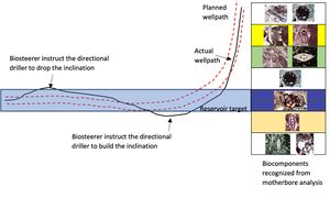
Biosteering offers a rapid assessment as to where the drilling bit is placed and through correlation with the current established biozonation scheme, biosteerers can forecast the bit trajectory and calculate the dip angle required for optimized reservoir contact complementing LWD tools or seismic data. There may be instances where the target reservoir is barren of microfossils. Recognizing the fossil assemblage above and below the reservoir layer will still aid in maintaining the well trajectory inside the reservoir. Once the biosteerer recognizes that fossil assemblages currently analyzed belong to the seal or the unit above the reservoir, the directional driller will be asked to drop the angle by certain degrees to continue drilling through the reservoir layer.
Method[edit]
A biosteering horizontal well is drilled through three distinctive stages: a buildup section, landing phase and the vertical section.
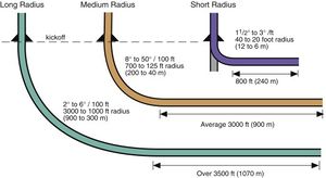
The buildup section is initiated after the kickoff point (KOP), a sidetrack where the well path deviates away from the vertical mother bore at an increasing angle. The drilling program will consist of KOP and a buildup rate, selected after examining the casing program, anticipating the formations that will be drilled, simulating the possible doglegs and drilling inclinations and assessing the horizontal displacement. The build rate depends on the radius of horizontal wells. Short radius horizontal wells will require higher angle build rates up to 50 degrees per 100 ft drilled. Normally, build rates can reach 6 degrees per 100 ft drilled.[13]
During this stage, the micropaleontologist onsite utilizes the GR signatures to trace the changes in formations or members and correlate these changes with the microfossil assemblage, calculating the thicknesses of layers and monitoring any discrepancies from the planned trajectory. In case of thinning or thickening of layers, the micropaleontologist will discuss adjusting the buildup rate with the directional driller.
The landing phase is the term used for placing the well path into the target reservoir layer at the proper desired angle. A successful landing requires proper monitoring of layers drilled during the buildup section and communicating any inconsistencies as soon as they are recognized. The micropaleontologist will confirm reservoir entry from the samples analyzed.
After landing the well, the vertical section (VS) which is the horizontal distance drilled away from the motherbore begins. The biostratigraphic scheme becomes essential at this stage since forecasting the well trajectory relies heavily on the analyzed samples. The biosteerer will be responsible for calculating any layer dip variations along the vertical section and reporting them to the modelling group to adjust their field model grids.
While drilling the vertical section, the drilling angle will experience changes in both inclination and azimuth. This happens due to the heterogeneous nature of the reservoir incurred from secondary diagenetic effects, changes in reservoir biofacies, hardness of layers, structural changes or local pinch-outs. Dogleg severity (DLS) is the term used to measure the directional angle changes over specific footage drilled. It is critical to maintain low DLS throughout the vertical section to maximize footage drilled and avoid earlier lock-ups, a critical point where coil tube drilling cannot proceed any further.[14] Avoiding early lock-ups helps the micropaleontologist to maximize the reservoir contact.
Biosteering is not limited to maximizing reservoir contact. The application can be used for water injection operations or reserve estimations. In Nigeria, biosteering was used to pilot the hole along the oil-water contact with full accuracy. Bed thicknesses differed from prognosed but precise monitoring of well trajectory made ensured successful operation.[1]
Calculations[edit]
Calculating the dip and the bed inclination is a very critical aspect in biosteering wells. Biosteering use formation dip to communicate the required drilling angle while the driller uses inclination (INC). In a horizontal well, 3 degrees up-dip is translated into 93 degrees bed inclination. There are multiple methods that allow estimation of bed inclination:
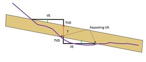
- Observing a repeated GR signature from the logs. When a mirroring signature appears in the logs, the bedding inclination can be calculated using a simple trigonometry equation:
Tan (x) = ∆ TVD ÷ ∆ VS
The use of the aforementioned equation is not limited to repeating GR signatures. With an extremely detailed biostratigraphic scheme, the equation can be used on repeating biozones as well. However, it is not recommended when there is expectation of reservoir lateral heterogeneity.
- When bed thickness is known, a slight change from the aforementioned equation can be used to calculate the bedding inclination:
Tan (x) = (∆ TVD – T) ÷ ∆ VS
In both equations, TVD is the total vertical depth while T is the bed vertical thickness.
Limitations[edit]
Although biosteering is a very effective method when steering horizontal wells, there are some limitations. One example is cutting contamination; cuttings received on surface are not directly tied to the actual lag depth and are mixed with cuttings drilled shallower. Cutting contaminations influence the biostratigraphic interpretations and may confuse the biosteerer without proper monitoring of changes in lag time, GR readings and the biofacies analyzed. Usually poor hole cleaning conditions whether due to low pressures or the use of fluids affect the quality of the extracted drilled cuttings and how frequent they travel to the surface. The type of drilling bit used for drilling is another factor that may affect the quantity and quality of cuttings recovered on surface. Drillstring rotation, mud properties and ROP can all impact the hole condition negatively. Therefore, increasing the flow rate as well as performing frequent wiper trips can sustain good hole conditions.
Accomplishments in Saudi Arabia[edit]
Biosteering has been implemented in Saudi Arabia for over 13 years. During the time, UBCTD managed to biosteer over 1000000 ft maintaining a reservoir contact of over 90%. Most biosteered UBCTD was performed in Permian Khuff reservoirs, though there were in-house studies to see how effective biosteering can be in Middle Jurassic reservoirs.
See also[edit]
References[edit]
- ↑ 1.0 1.1 1.2 1.3 Fadiya, S. L. 2014. Impact of wellstie biostratigraphy on exploration drilling in the deepwater offshore Nigeria. Journal of African Earth Sciences 100: 60 – 69.
- ↑ Shipp, D. J. 1999. Well-site biostratigraphy of Danish horizontal wells. Geological Society London, Special publications 152: 75 – 84.
- ↑ Jones, R. W., Lowe, S., Milner, P., Heavey, P., Payne, S. & Ewen, D. 2005. The role and value of “biosteering” in hydrocarbon reservoir exploitation. In Koutsoukos, E. A. M. (ed.). Applied Stratigraphy, 339 – 355. Springer.
- ↑ Holmes, N. A. 1999. The Andrew formation and ‘biosteering’ – different reservoirs, different approaches. Geological Society London, Special publications 152: 155 – 166.
- ↑ Yang-Logan, L. C., Tveit, R. & Bailey, H. W. 1995. Biosteering – A biostratigraphic application to horizontal drilling in the Eldfisk field, Norwegian North Sea. United States.
- ↑ Shipp, D. J. & Marshall, P. R. 1994. Biostratigraphic steering of horizontal wells. In Al-Husseini, M. I. (ed.). The Middle East Petroleum Geosciences. Selected Middle East Papers from the Middle East Geoscience Conference 2: 849 – 860. Manama, Bahrain.
- ↑ Marshall, P. R., Burchette, T. & Ali, K. S. 2007. Integrated subsurface geology and biosteering: A case study from Sajaa field, Sharjah, UAE. International Petroleum Technology Conference, Dubai.
- ↑ Henderson, A. & Marshall, P. R. 2013. Biosteering in Margham field, onshore Dubai – A case study on significant updating of the static model during a UBCTD campaign. European Association of Geoscientists and Engineers. EAGE workshop on Geosteering and well placement.
- ↑ 9.0 9.1 Hughes, G. W., Boukhamsin, H., Al-Enezy, S., Rashid, S., Dhubaib, A. & Alqattan, M. 2019. Biosteering carbonate reservoirs – the upper Permian Khuff formation of Saudi Arabia. Stratigraphy 16: 107 – 117.
- ↑ Ladmia, A., Culen, M., Al Katheeri, A. B., Al Hosani, F. M., Edmonstone, G. F. Mantilla, A., Baslaib, M. A., Nabil, I. M., Yousfi, F. Z., Al Hosani, M. A., Almenhali, S. S., El Shahat, A., Abdulsallam, F., Al-Khatib, H. M., Al Jaberi, F. O., El Bishr, H. & Mcneilly, K. D. 2020. Underbalanced coiled tubing drilling in tight gas reservoir study case onshore field Abu Dhabi. Abu Dhabi International Petroleum Exhibition & Conference, Abu Dhabi, UAE.
- ↑ Matanovi, D. Meimurec, N. G & Kristafor, Z. 2000. Underbalanced drilling with coiled tubing. Abu Dhabi International Petroleum Exhibition & Conference, Abu Dhabi, UAE.
- ↑ Payne, S. N. J., Ewen, D. F. & Bowman, M. J. 1999. The role and value of ‘high-impact biostratigraphy’ in reservoir appraisal and development. In Jones, R. W., Simmons, M. D., (eds.). Biostratigraphy in production and development geology, Geological Society London, Special publication 152: 5–22.
- ↑ Jahn, F., Cook, M. and Grahm, M. 2008. Chapter 4 Drilling Engineering. In Jahn, F., Cook, M. and Grahm, M. (eds.). Hydrocarbon Exploration and Production, Development in Petroleum Science 55: 47-81.
- ↑ He, X. & Kyllingstad, A. 1995. Helical buckling and lock-up conditions for coiled tubing in curved wells. SPE drilling and completion 10. SPE Asia Pacific Oil and Gas Conference and Exhibition, Singapore.
