Difference between revisions of "Workovers"
Cwhitehurst (talk | contribs) |
Cwhitehurst (talk | contribs) m (added Category:Methods in Exploration 10 using HotCat) |
||
| (One intermediate revision by one other user not shown) | |||
| Line 14: | Line 14: | ||
}} | }} | ||
A ''workover'' is any operation done on, within, or through the wellbore after the initial completion. Although proper drilling, cementing, and completion practices minimize the need, virtually every well will need several workovers during its lifetime to satisfactorily fulfill its purpose. | A ''workover'' is any operation done on, within, or through the wellbore after the initial completion. Although proper drilling, cementing, and completion practices minimize the need, virtually every well will need several workovers during its lifetime to satisfactorily fulfill its purpose. | ||
| + | |||
| + | [[File:Pump Jack labelled.png|thumb|400px|A pump jack diagram. Courtesy [https://commons.wikimedia.org/wiki/File:Pump_Jack_labelled.png|Wikimedia Commons].]] | ||
To help understand why workovers are required, it is useful to visualize a wellbore. A typical wellbore schematic is shown in [[:file:workovers_fig1.png|Figure 1]]. The production casing is only 5 to [[length::9 in.]] in diameter, and it has been run into a corkscrew-shaped hole that is not entirely circular and may be substantially deviated from vertical. An attempt has been made to cement the casing centrally, at least across the productive intervals, to obtain a hydraulic seal and casing support. Inside the production casing, even smaller equipment is run for completion and production or injection purposes. [[:file:workovers_fig2.png|Figure 2]] illustrates the tight fit of these concentric strings. Although the diameters are small, the surface area of the equipment is significant and may be exposed to corrosive fluids and pressure for long periods of time. | To help understand why workovers are required, it is useful to visualize a wellbore. A typical wellbore schematic is shown in [[:file:workovers_fig1.png|Figure 1]]. The production casing is only 5 to [[length::9 in.]] in diameter, and it has been run into a corkscrew-shaped hole that is not entirely circular and may be substantially deviated from vertical. An attempt has been made to cement the casing centrally, at least across the productive intervals, to obtain a hydraulic seal and casing support. Inside the production casing, even smaller equipment is run for completion and production or injection purposes. [[:file:workovers_fig2.png|Figure 2]] illustrates the tight fit of these concentric strings. Although the diameters are small, the surface area of the equipment is significant and may be exposed to corrosive fluids and pressure for long periods of time. | ||
| Line 106: | Line 108: | ||
[[Category:Production engineering methods]] | [[Category:Production engineering methods]] | ||
| + | [[Category:Methods in Exploration 10]] | ||
Latest revision as of 15:25, 24 January 2022
| Development Geology Reference Manual | |

| |
| Series | Methods in Exploration |
|---|---|
| Part | Production engineering methods |
| Chapter | Workovers |
| Author | Alan F. Osborne |
| Link | Web page |
| Store | AAPG Store |
A workover is any operation done on, within, or through the wellbore after the initial completion. Although proper drilling, cementing, and completion practices minimize the need, virtually every well will need several workovers during its lifetime to satisfactorily fulfill its purpose.

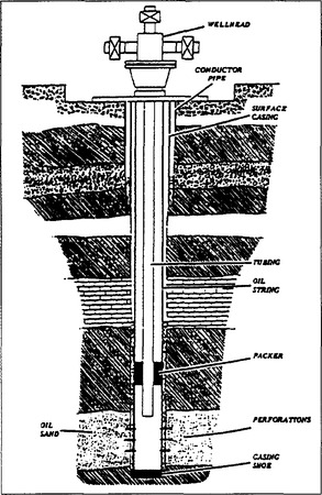
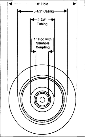
To help understand why workovers are required, it is useful to visualize a wellbore. A typical wellbore schematic is shown in Figure 1. The production casing is only 5 to length::9 in. in diameter, and it has been run into a corkscrew-shaped hole that is not entirely circular and may be substantially deviated from vertical. An attempt has been made to cement the casing centrally, at least across the productive intervals, to obtain a hydraulic seal and casing support. Inside the production casing, even smaller equipment is run for completion and production or injection purposes. Figure 2 illustrates the tight fit of these concentric strings. Although the diameters are small, the surface area of the equipment is significant and may be exposed to corrosive fluids and pressure for long periods of time.
Another visualization to keep in mind is the very small wellbore size relative to the reservoir area to be drained by that well. A minor restriction (such as scale, fines, paraffin, or pipe dope) at the wellbore has a significant effect on production rate and ultimate recovery.
Reasons for workovers
Workovers may be required for one or more of the following reasons:
- Unsatisfactory production or injection rates
- Supplemental recovery project requirements
- Regulatory requirements
- Competitive drainage
- Reservoir data gathering
- Lease requirements
- Abandonments
The majority of workovers are done because the well is not performing up to expectations (see Production problems). Careful analysis will determine if the decline is abnormal or the result of normal reservoir depletion. If deemed abnormal, it must be determined if the problem is in the reservoir inflow system, the wellbore outflow system, or both. Inflow problems can be corrected with stimulation procedures such as acidizing, fracturing, scale, or paraffin treatments (see Stimulation) or by reperforating or additional perforating. Outflow problem resolution may require equipment changes, cleanouts, or chemical treatments.
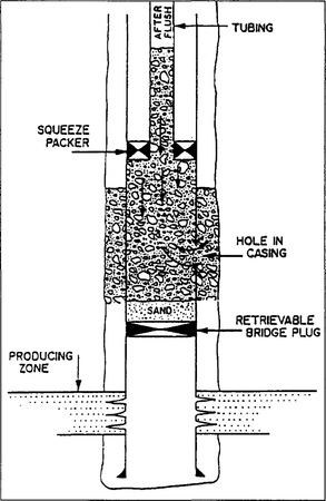
Mechanical problems such as failures of the cement, tubulars, packers, wireline components, safety valves, or artificial lift equipment are also reflected in the well performance. Cement and casing problems are most often corrected by squeezing cement into the damaged areas (Figure 3). Very serious problems of this nature occasionally require a sidetracking operation. Depending on the initial wellbore configuration, some mechanical problems can be corrected by applying wireline methods. More often, however, the equipment must be pulled using a rig. This may be a routine operation, but it may be a major task if the equipment is stuck or has parted downhole. To recover parted or stuck downhole equipment, a fishing operation may be required (see Fishing).
Initiation of supplemental recovery projects causes workovers because many wells must be converted to injectors, observation wells, or disposal wells. Also, all wells need to be completed in correlative zones, thus a significant number of wells need perforating and stimulation and/or zones shutoff via squeeze cementing or plugs (cement or mechanical).
Workovers done for the reasons just noted are generally completed to yield a profit in a reasonable length of time. Those done for the following reasons may have little profit incentive, but are still necessary for prudent, legal operations:
- Regulatory requirements may initiate workovers to reduce GORs, isolate pressures, or install safety equipment.
- Competitive conditions occasionally generate workovers designed to protect correlative rights, which often affects the timing more than the goal of doing that particular job.
- Data gathering, particularly of special reservoir information (such as pressures, fluid samples and zonal productivity/injectivity tests) required for reservoir management or in connection with pilot tests, may require a workover.
- The requirement to maintain production to hold a lease may encourage a workover to allow more time to determine proper lease disposition.
- Workovers are normally required to temporarily abandon or to plug and abandon a well. Operations may include squeeze cementing, setting plugs (cement or mechanical), retrieving production equipment, and perhaps cutting and pulling casing. Workover costs vary depending on well conditions and regulatory requirements.
Workover considerations
Although the considerations necessary to design a workover are virtually the same as those noted for standard well completions (see Well completions), some require special mention:
- Safety must receive special attention. The tendency to consider a workover as “routine” sometimes reduces the level of safety attentiveness.
- Well pressure may be a primary consideration. If the open zone has experienced significant depletion, the circulation of fluids becomes difficult or even impossible. The well killing process will introduce significant amounts of fluids into the reservoir with the potential for formation damage. If the wellbore is now open to high pressure, safety is of paramount importance. If existing well equipment has been in the well for a long time, it may not be capable of containing high shut-in pressure.
- In thermal projects, the elevated temperatures create special needs for doing a workover safely.
- The condition of the well equipment may be a major factor in what and how much is done in a particular workover. The toll taken by corrosion, erosion, and mechanical wear may be significant, particularly if the casing is involved. Extra funds and time may need to be allocated to cover potential squeeze cement jobs, fishing operations, and equipment replacement.
Types of workovers
To some degree, workovers are classified on the basis of the reasons for them (discussed earlier). Another way to describe types of workovers is to divide them into (1) jobs performed primarily to influence the reservoir and (2) jobs applied to the wellbore (including the cement) and its associated equipment. Workovers done primarily to influence the reservoir can be subdivided into (1) work done for the zone already open and (2) work done to shut off the existing zone in favor of opening a new zone, termed a recompletion.
Operations typically done in an existing zone may include stimulation, reperforating, perforating additional intervals, and plugging off unwanted perforations (because of high gas or water production).
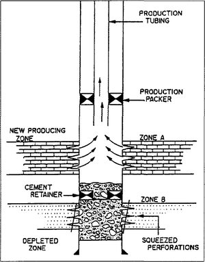
Recompletion work varies depending on whether the new zone is above or below the currently open zone. If above, the lower zone will be abandoned via squeeze cementing (Figure 4), a cement plug, or a mechanical bridge plug, and the zone of interest will be perforated and stimulated. Appropriate outflow equipment will then be installed. If the new zone is below, the existing zone will probably be squeeze cemented (in the same manner as repairing casing, as shown in Figure 3). The cement in the wellbore is drilled out, the lower zone perforated and stimulated, and production equipment run. Some wells have had sufficient well work done upon initial completion to permit recompletion by simply using a wireline to run plugs and open sleeves.
Wellbore workovers can include casing or equipment repair, but may also simply involve cleaning out fill over the producing zone or circulating chemicals to remove scale or paraffin.
Many workovers involve the installation, maintenance, and repair of artificial lift equipment in the wellbore. About 85% of the oil wells in the United States are on some form of artificial lift. Approximately 85% of those wells are on rod pump, 10% on gas lift, and 5% on submersible or hydraulic pumps. Rigs are required for most artificial lift workovers; however, many gas lift wells can be serviced with a wireline.
Workover equipment
Workovers can be done with conventional rigs (smaller but similar to drilling rigs) or nonconventional systems. Conventional rigs can be equipped to handle almost all types of work that may be required (see Land rigs). Nonconventional systems allow specific types of work to be done without pulling the tubing, disassembling the Christmas tree, or even killing the well. This is accomplished by using lubricators and packoff equipment at the surface and by running the required equipment inside the production tubing. Common types of nonconventional systems are wireline units, coiled tubing units, and snubbing units. Generally, these systems are designed to do a relatively narrow scope of work.
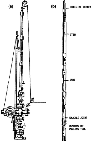
Wireline units use special equipment (Figure 5) on a solid wireline to gather data (pressure, temperature, and depth) and to set, manipulate, and/or retrieve tubing plugs, sliding sleeves, flow regulators, gas lift valves, safety valves, and wireline fishing tools. Wireline equipment can also be used to cut paraffin and remove wellbore fill. Prior planning, good operators, good equipment, and reasonable well conditions are prerequisites to the success of this method.
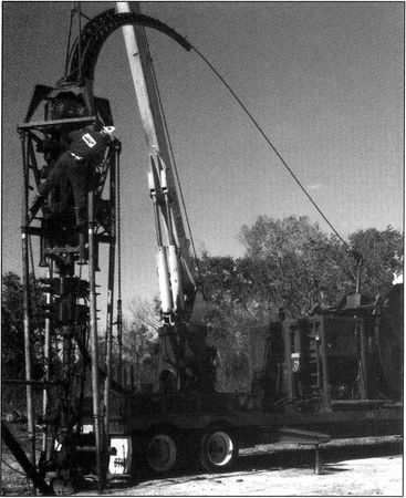
Coiled tubing units (Figure 6) find application in cleanout work, stimulation, plugback jobs, and unloading wells with nitrogen. Coiled tubing units can have 10,000 to depth::15,000 ft of pipe (usually 1-in. outside diameter) that can be reeled continuously into the wellbore. The pipe can be used to pump into the well and circulate fluids such as water, acid, or cement. The use of a dynadrill permits some drilling with coiled tubing. Limitations of coiled tubing include the reduced strength of the tubing and low pumping rates (high friction pressure because of the diameter and length). Coiled tubing can be run into wells against pressures up to 5000 psi.
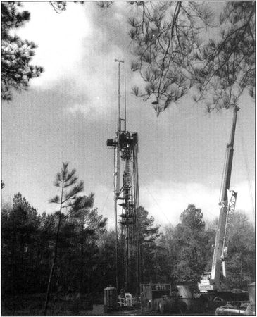
Snubbing units (Figure 7) use hydraulic pressure and rams to introduce small, coupled tubing into the well, if necessary, against pressures above 5000 psi. The tubing is stronger and can be rotated so that tougher cleanout or fishing jobs can be accomplished. Snubbing units are used for the same type of jobs as are coiled tubing units, but their compactness is an advantage in offshore work. They are slow and expensive, but in the right applications, they are the more economical way to accomplish the task.
See also
- Production testing
- Production histories
- Artificial lift
- Surface production equipment
- Stimulation
- Introduction to production engineering methods
- Pressure transient testing
- Well completions
- Production logging
- Production problems
