Difference between revisions of "Deltaic reservoirs"
Cwhitehurst (talk | contribs) |
Cwhitehurst (talk | contribs) |
||
| (3 intermediate revisions by the same user not shown) | |||
| Line 44: | Line 44: | ||
| Stacked distributary channels || Larger sand bodies with good vertical connectivity and sweep || - | | Stacked distributary channels || Larger sand bodies with good vertical connectivity and sweep || - | ||
|- | |- | ||
| − | | Mouth bars contain extensive mudstone laminae || - || Mouth bars may have poor vertical connectivity and sweep | + | | Mouth bars contain extensive [[mudstone]] laminae || - || Mouth bars may have poor vertical connectivity and sweep |
|- | |- | ||
| Stacked mouth bars || Larger sand bodies with good vertical connectivity and sweep || - | | Stacked mouth bars || Larger sand bodies with good vertical connectivity and sweep || - | ||
| Line 57: | Line 57: | ||
==Deltas are often gas reservoirs== | ==Deltas are often gas reservoirs== | ||
Many deltaic reservoirs, particularly long-lived Tertiary to present-day delta areas, contain more gas than oil. This is because they can be particularly rich in [[coal]]s and woody [[kerogen]], which form gas-prone humic source material. Gas fields are found in the Mackenzie, Nile, and Irrawady deltas, for instance. Deltas can contain oil or mixed oil and gas where sandstones interfinger with a marine source rock.<ref name=Gallowayandhobday_1996>Galloway, W. E., and D. K. Hobday, 1996, Terrigenous clastic depositional systems: Applications to petroleum, coal, and uranium exploration: New York, Springer-Verlag, 489 p.</ref> | Many deltaic reservoirs, particularly long-lived Tertiary to present-day delta areas, contain more gas than oil. This is because they can be particularly rich in [[coal]]s and woody [[kerogen]], which form gas-prone humic source material. Gas fields are found in the Mackenzie, Nile, and Irrawady deltas, for instance. Deltas can contain oil or mixed oil and gas where sandstones interfinger with a marine source rock.<ref name=Gallowayandhobday_1996>Galloway, W. E., and D. K. Hobday, 1996, Terrigenous clastic depositional systems: Applications to petroleum, coal, and uranium exploration: New York, Springer-Verlag, 489 p.</ref> | ||
| − | |||
| − | |||
| − | |||
| − | |||
==Types of delta== | ==Types of delta== | ||
Deltas have been categorized into three classes in terms of sedimentary process: wave dominated, tidal dominated, and fluvial dominated ([[:file:M91FG185.JPG|Figure 2]]).<ref name=Galloway_1975>Galloway, W. E., 1975, Process framework for describing the morphologic and stratigraphic evolution of deltaic depositional systems, in M. L. Broussard, ed., Deltas, models for exploration: Houston Geological Society, p. 87–98.</ref> Coarse-grained deltas include fan deltas and braid deltas. Each specific environment has its own geometries and typical reservoir characteristics. The geometrical patterns shown by the various types of delta can often be recognized on isochore, net-sand, and log-facies maps.<ref name=Colemanandwright_1975>Coleman, J. M., and L. D. Wright, 1975, Modern river deltas: Variability of processes and sand bodies, in M. L. Broussard, ed., Deltas, models for exploration: Houston Geological Society, p. 99–149.</ref> For example, a wave-dominated delta will show a T motif on these maps as a result of fluvial lineaments converging at a high angle to a shoreline trend (see [[:file:M91Ch11FG71.JPG|Figure 3]]). The lobate shape of the delta front may also be recognized. | Deltas have been categorized into three classes in terms of sedimentary process: wave dominated, tidal dominated, and fluvial dominated ([[:file:M91FG185.JPG|Figure 2]]).<ref name=Galloway_1975>Galloway, W. E., 1975, Process framework for describing the morphologic and stratigraphic evolution of deltaic depositional systems, in M. L. Broussard, ed., Deltas, models for exploration: Houston Geological Society, p. 87–98.</ref> Coarse-grained deltas include fan deltas and braid deltas. Each specific environment has its own geometries and typical reservoir characteristics. The geometrical patterns shown by the various types of delta can often be recognized on isochore, net-sand, and log-facies maps.<ref name=Colemanandwright_1975>Coleman, J. M., and L. D. Wright, 1975, Modern river deltas: Variability of processes and sand bodies, in M. L. Broussard, ed., Deltas, models for exploration: Houston Geological Society, p. 99–149.</ref> For example, a wave-dominated delta will show a T motif on these maps as a result of fluvial lineaments converging at a high angle to a shoreline trend (see [[:file:M91Ch11FG71.JPG|Figure 3]]). The lobate shape of the delta front may also be recognized. | ||
| + | |||
| + | <gallery mode=packed heights=450px widths=450px> | ||
| + | file:M91FG185.JPG|{{figure number|2}}Three categories of delta can be defined according to the dominant sedimentary process. These are wave-dominated, tide-dominated, and fluvial-dominated deltas. Courtesy of the [http://www.earthobservatory.com NASA Web site]. | ||
| + | file:M91Ch11FG71.JPG|{{figure number|3}} A gross sandstone thickness map can give an idea of the depositional dip and strike of the sedimentary system. In the Budare field of Venezuela, north–south strike elements correspond to distributary channels in the bottom part of the map. An east–west arcuate depositional element in the north of the map corresponds to a wave-dominated delta front (from Hamilton et al.<ref name=Hamiltonetal_2002>Hamilton, D. S., et al., 2002, [http://archives.datapages.com/data/bulletns/2002/07jul/1237/1237.htm Reactivation of mature oil fields through advanced reservoir characterization: A case history of the Budare field, Venezuela]: AAPG Bulletin, v. 86, no. 7, p. 1237–1262.</ref>). | ||
| + | </gallery> | ||
==Depositional environments== | ==Depositional environments== | ||
| Line 93: | Line 94: | ||
Sand is deposited within linear distributary channels as side bars. In the modern-day Mahakam Delta, Borneo, side bars alternate on both sides of the distributary channels. These form elliptical sand pods, 5–8 km (3–5 mi) or more long and up to 1 km (0.6 mi) wide.<ref name=Allenandchambers_1998>Allen, G. P., and J. L. C. Chambers, 1998, Sedimentation in the modern and Miocene Mahakam delta: Indonesian Petroleum Association, 236 p.</ref> Channel fills typically show an upward-fining sediment profile and an upward-decreasing permeability profile. From the base upward, a distributary channel comprises the active channel fill, showing decimeter-scale trough cross-bedded sets; a partial abandonment fill with mainly centimeter-scale cross-beds; and sometimes an abandonment channel fill of thinly interbedded fine sand, silt, and shale. | Sand is deposited within linear distributary channels as side bars. In the modern-day Mahakam Delta, Borneo, side bars alternate on both sides of the distributary channels. These form elliptical sand pods, 5–8 km (3–5 mi) or more long and up to 1 km (0.6 mi) wide.<ref name=Allenandchambers_1998>Allen, G. P., and J. L. C. Chambers, 1998, Sedimentation in the modern and Miocene Mahakam delta: Indonesian Petroleum Association, 236 p.</ref> Channel fills typically show an upward-fining sediment profile and an upward-decreasing permeability profile. From the base upward, a distributary channel comprises the active channel fill, showing decimeter-scale trough cross-bedded sets; a partial abandonment fill with mainly centimeter-scale cross-beds; and sometimes an abandonment channel fill of thinly interbedded fine sand, silt, and shale. | ||
| − | |||
| − | |||
| − | |||
| − | |||
==Mouth bars== | ==Mouth bars== | ||
| Line 143: | Line 140: | ||
| colspan="11" | *''From Reynolds.<ref name=Reynolds_1999 /> N = number.'' | | colspan="11" | *''From Reynolds.<ref name=Reynolds_1999 /> N = number.'' | ||
|} | |} | ||
| + | <gallery mode=packed heights=450px widths=400px> | ||
| + | file:M91FG123.png|{{figure number|4}}A schematic delta showing a range of sand body types at their average dimensions, together with several oil and gas fields at the same scale. The delta front is divided into three segments that are storm-, fluvial-, and tidal-dominated, respectively. The delta and its divisions are not to scale (from Reynolds<ref name=Reynolds_1999>Reynolds, A. D., 1999, [http://archives.datapages.com/data/bulletns/1999/02feb/0211/0211.htm Dimensions of paralic sandstone bodies]: AAPG Bulletin, v. 83, no. 2, p. 211–229.</ref>). | ||
| + | file:M91FG186.JPG|{{figure number|5}}Fluvial-dominated delta environment, Mississippi Delta. Photograph courtesy of the [http://www.earthasart.gsfc.nasa.gov NASA Web site]. The inset box on the photograph measures 34 times 42 km (21 times 26 mi). The lower diagram is a box diagram showing the sedimentological relationships within the inset box (after Fisk<ref name=Fisk_1961>Fisk, H. N., 1961, [http://archives.datapages.com/data/specpubs/sandsto1/data/a055/a055/0001/0000/0029.htm Bar-finger sands of the Mississippi delta], in J. A. Peterson and J. C. Osmond, eds., Geometry of sandstone bodies: AAPG Symposium, SP22, p. 29–52.</ref>). | ||
| + | </gallery> | ||
[[file:M91FG187.JPG|thumb|300px|{{figure number|6}}Idealized log and permeability profiles for deltaic sand bodies (from Sneider et al.<ref name=Sneideretal_1978 />). Reprinted with permission from, and © by, the Society of Petroleum Engineers.]] | [[file:M91FG187.JPG|thumb|300px|{{figure number|6}}Idealized log and permeability profiles for deltaic sand bodies (from Sneider et al.<ref name=Sneideretal_1978 />). Reprinted with permission from, and © by, the Society of Petroleum Engineers.]] | ||
| Line 202: | Line 203: | ||
[[Distributary channel]]s tend to be narrow with a common width range of 10–300 m (33–984 ft).<ref name=Gibling_2006 /> It is possible that hydrocarbons in isolated distributary channels may be missed in fields with larger well spacings. Richardson et al.<ref name=Richardsonetal_1989 /> stated that it could be impractical to try and locate both injection and production wells to sweep individual distributary channels. The sweep efficiency in the distributary channels will be low without direct injection support, particularly if the sand bodies are isolated. There is a better chance of improving recovery by waterflooding the delta-front sandstones. | [[Distributary channel]]s tend to be narrow with a common width range of 10–300 m (33–984 ft).<ref name=Gibling_2006 /> It is possible that hydrocarbons in isolated distributary channels may be missed in fields with larger well spacings. Richardson et al.<ref name=Richardsonetal_1989 /> stated that it could be impractical to try and locate both injection and production wells to sweep individual distributary channels. The sweep efficiency in the distributary channels will be low without direct injection support, particularly if the sand bodies are isolated. There is a better chance of improving recovery by waterflooding the delta-front sandstones. | ||
| − | ==Sweep | + | ==Sweep patterns in delta-front sediments== |
Sneider et al.<ref name=Sneideretal_1978 /> showed how considerable flow complexity can be present in the delta-front environment. This results from the incision of fining-upward channels into coarsening-up mouth bars. The coarser basal sections of the channels act as permeability fairways for water ingress to production wells with the potential to leave oil bypassed within the finer grained parts of the mouth bars. Similar sweep patterns were noted by Hartman and Paynter<ref name=Hartmanandpaynter_1979 /> in Tertiary fluviodeltaic sandstones in fields offshore of Louisiana ([[:file:M91FG190.JPG|Figure 9a]]). | Sneider et al.<ref name=Sneideretal_1978 /> showed how considerable flow complexity can be present in the delta-front environment. This results from the incision of fining-upward channels into coarsening-up mouth bars. The coarser basal sections of the channels act as permeability fairways for water ingress to production wells with the potential to leave oil bypassed within the finer grained parts of the mouth bars. Similar sweep patterns were noted by Hartman and Paynter<ref name=Hartmanandpaynter_1979 /> in Tertiary fluviodeltaic sandstones in fields offshore of Louisiana ([[:file:M91FG190.JPG|Figure 9a]]). | ||
Latest revision as of 13:46, 26 August 2024
| Oil Field Production Geology | |

| |
| Series | Memoirs |
|---|---|
| Part | The Production Geologist and the Reservoir |
| Chapter | Deltaic reservoirs |
| Author | Mike Shepherd |
| Link | Web page |
| PDF file (requires access) | |
| Store | AAPG Store |
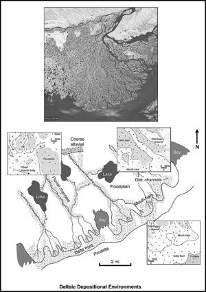
Deltas are major sites of sand and mud deposition. They contain significant volumes of hydrocarbons worldwide (Figure 1). Major petroleum provinces include the Niger Delta in west Africa, the Mahakam Delta in Borneo, the Caspian Sea, and the Maracaibo Basin in Venezuela.
Deltaic sediments often form complex reservoirs
Delta systems make heterogeneous reservoirs, typically with a jigsaw-puzzle to labyrinthine sediment geometry (Table 1). There may also be considerable structural complexity. Many rivers, particularly the larger ones, dump very large quantities of sediment into deltas on top of an unstable substrate containing mobile salt and/or shale. Salt deformation features and growth faulting are common in deltaic sediments, and these can result in numerous segmented reservoirs, such as in the Tertiary Niger Delta in west Africa.[2][3]
| Characteristic | Favorable for reservoir development | Unfavorable for reservoir development |
|---|---|---|
| Growth faults common | - | Numerous sealing fault compartments |
| Shingled geometry | - | Results in bypassed oil in individual shingles |
| Increasing marine reworking of delta front | Creates increasing lateral connectivity in the delta-front sediments | - |
| Wave-dominated delta | More continuous, may have an aquifer | - |
| Fluvial-dominated delta | - | Can show low recoveries caused by labyrinthine geometry |
| Tidal-dominated delta | - | Low recoveries caused by complex geometry and numerous mud and silt baffles |
| Distributary channels form narrow sand bodies | - | May be missed by wells in fields with a large well spacing; difficult to locate injection wells |
| Distributary channel sands commonly the highest permeability facies association in deltas | Can be the most productive intervals in a delta | - |
| Stacked distributary channels | Larger sand bodies with good vertical connectivity and sweep | - |
| Mouth bars contain extensive mudstone laminae | - | Mouth bars may have poor vertical connectivity and sweep |
| Stacked mouth bars | Larger sand bodies with good vertical connectivity and sweep | - |
| Mouth bars separated vertically by shales | Individual mouth bars can be targeted by horizontal wells; shale prevents water influx from swept units above and below | Poor to no vertical connectivity between mouth bars |
| Coarser grained distributary channels cutting finer-grained delta-front sandstones | - | Can result in preferential water ingress into the delta-front area, bypassing oil in the delta-front sediments |
| Peripheral strand-plain complexes with high frequency marine shales | - | Poor vertical sweep with potential for bypassed oil |
Deltas are often gas reservoirs
Many deltaic reservoirs, particularly long-lived Tertiary to present-day delta areas, contain more gas than oil. This is because they can be particularly rich in coals and woody kerogen, which form gas-prone humic source material. Gas fields are found in the Mackenzie, Nile, and Irrawady deltas, for instance. Deltas can contain oil or mixed oil and gas where sandstones interfinger with a marine source rock.[4]
Types of delta
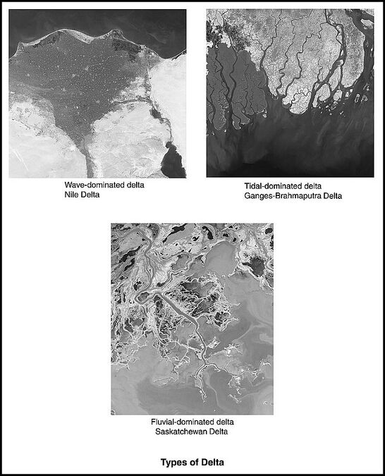
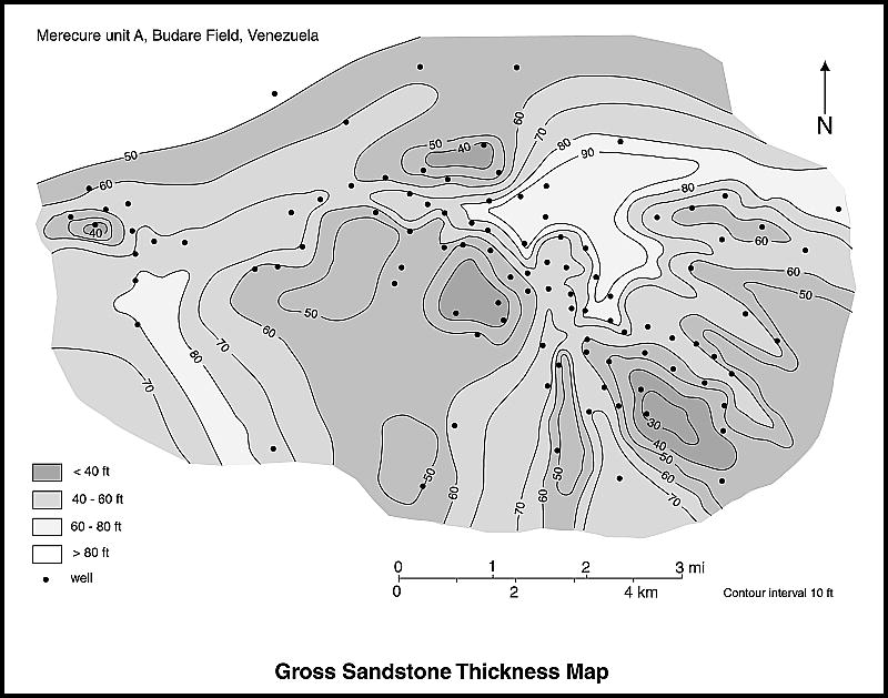
Deltas have been categorized into three classes in terms of sedimentary process: wave dominated, tidal dominated, and fluvial dominated (Figure 2).[5] Coarse-grained deltas include fan deltas and braid deltas. Each specific environment has its own geometries and typical reservoir characteristics. The geometrical patterns shown by the various types of delta can often be recognized on isochore, net-sand, and log-facies maps.[6] For example, a wave-dominated delta will show a T motif on these maps as a result of fluvial lineaments converging at a high angle to a shoreline trend (see Figure 3). The lobate shape of the delta front may also be recognized.
Figure 2 Three categories of delta can be defined according to the dominant sedimentary process. These are wave-dominated, tide-dominated, and fluvial-dominated deltas. Courtesy of the NASA Web site.
Figure 3 A gross sandstone thickness map can give an idea of the depositional dip and strike of the sedimentary system. In the Budare field of Venezuela, north–south strike elements correspond to distributary channels in the bottom part of the map. An east–west arcuate depositional element in the north of the map corresponds to a wave-dominated delta front (from Hamilton et al.[7]).
Depositional environments
The influence of river, wave, and tide on deltaic sediments produces a complex mix of macroforms. Fluvial processes dominate in the upper delta plain, although this area can also be swampy with marshes and lakes present. The lower delta plain is subjected to marine influence, acting to modify the fluvial-derived sediments. Delta fronts comprise nested complexes of distributary channels, mouth bars, tidal bars, and reworked delta-front sediments (Figure 1).
Distributary channels
Distributary channels are so called because of the way in which they branch off from the main feeder river and distribute water and sediment across the delta. Where the distributary channels split off from the main feeder river, the volume of water carried by individual channels will be a fraction of that in the main river. By comparison to fluvial channels, distributary channels tend to be narrower and shallower. Gibling[8] noted that distributary channels show a common width range of 10–300 m (33–984 ft) (see Table 2). Distributary channels tend to be straight where they incise a mud substrate and more sinuous within a sand substrate.[9]
| Depositional environment | Thickness | Width | Width/thickness ratio |
|---|---|---|---|
| Braided and low sinuousity rivers | 1-1200 m (3-3937 ft); most < 60 m (197 ft); common range 5-60 m (16-197 ft) | 50 m-1300+ km (164 ft-808+ mi); many > 1 km (0.62 mi); common range 0.5-10 km (0.3-6 mi) | 15-15,000+; some > 1000; common range 50-1000 |
| Meandering rivers | 1-38 m (3-125 ft); common range 4-20 m (13-65 ft) | 30 m-15 km (98 ft-9 mi); most < 3 km (1.8 mi); common range 0.3-3 km (0.1-1.8 mi) | 7-940; most < 250; many < 100; common range 30-250 |
| Delta distributaries | 1-35 m (3-115 ft); most < 20 m (65 ft); common range 3-20 m (10-65 ft) | 3 m-1 km (10 ft-0.6 mi); most < 500 m (1640 ft); common range 10-300 m (33-984 ft) | 2-245; most < 50; many < 15; common range 5-30 |
| Channels in eolian settings | 1-19 m (3-62 ft) | 2.5-1500 m (8.2-4921 ft); most < 150 m (492 ft) | 1-90; most < 15 |
| Valley fills on bedrock unconformities | 12-1400 m (39-4593 ft); most < 500 m (1640 ft) | 75 m-52 km (246 ft-32 mi); most < 10 km (6 mi) | 2-870; highly variable; mainly 2-100 |
| Valley fills within alluvial and marine strata | 2-210 m (6-689 ft); most < 60 m (197 ft) | 0.1-105 km (0.06-65 mi); common range 0.2-25 km (0.1-15 mi) | 4.6-3640; highly variable; common range 10-1000; many from 100 to 1000 |
| 1From Gibling,[8] Journal of Sedimentary Research. Reprinted with permission from, and © by, the SEPM (Society for Sedimentary Geologists). | |||
Sand is deposited within linear distributary channels as side bars. In the modern-day Mahakam Delta, Borneo, side bars alternate on both sides of the distributary channels. These form elliptical sand pods, 5–8 km (3–5 mi) or more long and up to 1 km (0.6 mi) wide.[10] Channel fills typically show an upward-fining sediment profile and an upward-decreasing permeability profile. From the base upward, a distributary channel comprises the active channel fill, showing decimeter-scale trough cross-bedded sets; a partial abandonment fill with mainly centimeter-scale cross-beds; and sometimes an abandonment channel fill of thinly interbedded fine sand, silt, and shale.
Mouth bars
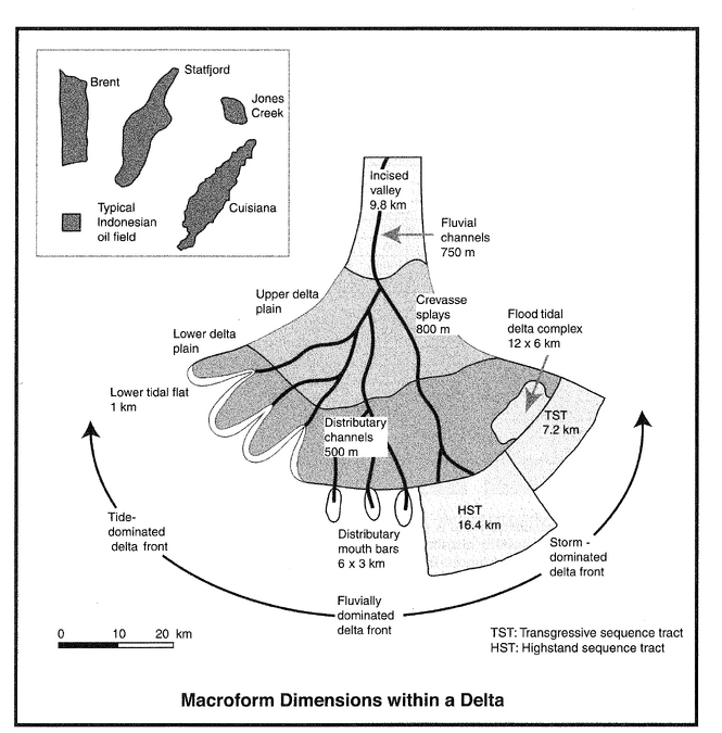
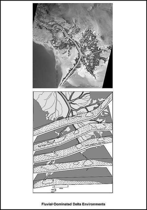
Mouth bars form where a distributary channel enters a standing body of water and sediment drops out. A shoaling to emergent sand body grows at the channel mouth. The resulting obstruction can cause the channel to bifurcate at the upstream head of the mouth bar. Mouth bars show an arcuate fan shape in plan view and a wedge-shaped profile in cross section. Reynolds[11] gave average dimensions for mouth bars of about 3 km (1.8 mi) wide and about 6.5 km (4 mi) long (see Figure 4; Table 3). Relatively straight distributary channels building out into deep water will form more linear deposits known as bar fingers (Figure 5).[12]
| Sand body type | Width | Length | Thickness | |||||||
|---|---|---|---|---|---|---|---|---|---|---|
| Mean | Max. | Min. | Mean | Max. | Min. | Mean | Max. | Min. | N | |
| Incised valleys | 9843 | 63,000 | 500 | - | - | - | 30.3 | 152 | 2 | 91 |
| Fluvial channels | 755 | 1400 | 57 | - | - | - | 9 | 24 | 2.5 | 6 |
| Distributary channels | 518 | 5900 | 20 | - | - | - | 7.8 | 40 | 1 | 268 |
| All types of systems tracts | 25,365 | 106,000 | 1600 | 93,166 | 190,000 | 47,000 | 19.1 | 49 | 2.7 | 67 |
| Highstand systems tract | 16,425 | 43,000 | 16,000 | - | - | - | - | - | - | 36 |
| Transgressive systems tract | 7150 | 20,000 | 3300 | - | - | - | - | - | - | 5 |
| Distributary mouth bars | 2868 | 14,000 | 1100 | 6477 | 9600 | 2400 | 9.7 | 42 | 1.2 | 26 |
| Flood tidal delta complex | 6201 | 13,700 | 1700 | 12,300 | 25,700 | 2900 | 6.7 | 23 | 1.8 | 13 |
| Crevasse channels | 58 | 400 | 5 | - | - | - | 2.4 | 17 | 0.2 | 44 |
| Crevasse splays | 787 | 7700 | 18 | 5577 | 11,700 | 160 | 1.4 | 12 | 0.3 | 84 |
| Lower tidal flat | 994 | 1550 | 400 | - | - | - | 4.6 | 9 | 2 | 14 |
| Tidal creeks | 813 | 1550 | 161 | - | - | - | 5.2 | 18 | 1 | 15 |
| Tidal inlet | 1850 | 2550 | 700 | 4300 | 4300 | - | 4.8 | 7 | 3 | 3 |
| Estuary mouth shoal | 2400 | 2900 | 1700 | 3750 | 4700 | 2200 | 10 | 35 | 10 | 4 |
| Chenier | 3650 | 6400 | 900 | 21,758 | 38,600 | 49,000 | 5.8 | 7 | 4.6 | 2 |
| All sands | 5094 | 106,000 | 5 | 35,313 | 190,000 | 160 | - | - | - | 671 |
| *From Reynolds.[11] N = number. | ||||||||||
Figure 4 A schematic delta showing a range of sand body types at their average dimensions, together with several oil and gas fields at the same scale. The delta front is divided into three segments that are storm-, fluvial-, and tidal-dominated, respectively. The delta and its divisions are not to scale (from Reynolds[11]).
Figure 5 Fluvial-dominated delta environment, Mississippi Delta. Photograph courtesy of the NASA Web site. The inset box on the photograph measures 34 times 42 km (21 times 26 mi). The lower diagram is a box diagram showing the sedimentological relationships within the inset box (after Fisk[12]).
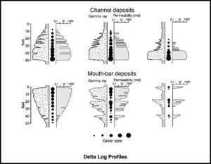
An upward-increasing grain size profile is characteristic for mouth bars. The lower parts are finer grained, more poorly sorted, and with common shale intercalations. Upward, the texture is coarser although there may be many laminations of clays and organic material. Permeability typically increases upward (Figure 6).
Mouth bars usually show lower overall permeabilities than distributary channel fills.[13] For example, Tye et al.[1] gave average rock property values for the various lithofacies associations within the Ivishak Formation of the Prudhoe Bay field in Alaska. The mouth bars have a mean permeability of 151 md compared to 315 md for the distributary channel fills.
The coarsest and best sorted sediments in the mouth bars form near the stream mouth and along the bar margins adjacent to the distributary channels. Tye and Hickey[14] found an order of magnitude higher permeability in this part of the point bars in Prudhoe Bay field, Alaska. Outward and down slope, the sediment becomes finer grained. Downstream, along the outer edge of the mouth bar, fine sand and silts interfinger with prodelta muds.
Delta front
The delta front area comprises a jigsaw-puzzle to labyrinthine complex of channel sandstones, mouth bars, and sediments formed by marine reworking. Wave, tidal, and fluvial processes act to rework the sediments on the delta front.
Wave reworking tends to produce relatively smooth lobate delta fronts. As the degree of wave reworking of the isolated mouth bars increases, the sediments become more continuous, coalescing to form laterally extensive beach-ridge and coastal-barrier sand bodies. The outlines of individual mouth bar forms start to become indistinct as they are reworked. Sometimes the sites of mouth bar deposition may only be recognizable by local thickening of the delta front.[4]
Delta-front sandstones tend to be finer grained, although better sorted, than distributary channel-fill sandstones. Later stage channels may cut into or overlie mouth bars and delta-front sandstones, creating jigsaw-puzzle geometrical complexity. Laterally and offshore, the sandstones become interbedded with background prodelta mudstones and will pinch out into them. The sandstone quality deteriorates laterally toward the margins.
Transgressive sandstones
Delta lobes will persist as areas of active sedimentation for a period of time, eventually becoming abandoned once the locus of sediment input switches elsewhere. The lobe eventually founders as a result of subsidence and a marine transgression follows. The transgressive sediments are thin, forming a distinctive facies association consisting of a series of coarse-grained, shelly beach ridges and barrier-bar inlet complexes.[4] These units are laterally extensive and can be important marker beds in delta systems where the reservoir comprises stacked delta lobes. The generally heterogeneous nature of delta sediments can make correlation difficult otherwise. Other important marker horizons are thin marine shales, impure limestones, and coal beds.
Tidal processes
Tidal deltas are deltas where tidal flow is important in the reworking of the delta front. Tidal currents ebb and flow out of the channel mouths creating tidal sand flats, sand ridges, and shoals that may be isolated within prodelta muds. Elongate sandstone bodies, broadly perpendicular to the shoreline, form at the seaward end of many tide-dominated deltas. These sand bodies can be tens of meters thick, several kilometers wide, and several tens of kilometers long.[15]
Tidal channels are commonly branched, with the branches tending to converge down stream. The channel fills comprise multiple stacked, fining-upward depositional units with abundant intercalated mud and silt drapes. Individual sand bodies are complex in architecture with numerous mud baffles and barriers. Given the heterogeneity of these systems, oil recover can be poor from tidal delta sediments.
Mudstones in deltas
Weber[16] stated that shales are not so laterally extensive in deltas by comparison to shoreface systems as fluvial and tidal channels commonly erode them. In distributary channels, the shale breaks can be short, commonly less than 10 m (33 ft) laterally.
Mudstones may be more extensive along the delta front. Tye et al.[1] found that mudstones deposited following delta lobe abandonment formed locally significant flow barriers between delta lobes within the Ivishak Formation, the basal reservoir interval of the Prudhoe Bay field in Alaska.
Shingled geometry of deltas
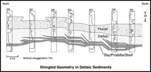
Shingled geometries are common in deltas (Figure 7). Shingled motifs may be seen on regional seismic lines and large-scale correlation diagrams.[17] There is evidence from some fields that the shingled patterns can result in compartmentalization and bypassed oil volumes; for example, the Teal field, offshore Louisiana,[18][19] the Sirikit field, onshore Thailand,[20] and the Ivishak Formation of the Prudhoe Bay field, Alaska.[1]
Coarse-grained deltas
Fan deltas
Fan deltas are coarse-grained deltas that form where alluvial fans deliver sediments into a lake or the sea. Geometries vary from wedging to tabular to sheet-like. Dreyer[21] described exposures of fan-delta sediments in the Miocene Ridge Route Formation of California as an analog for the Tilje Formation of the mid-Norwegian shelf. The main permeability barriers occur as transgressive prodelta mudstones separating individual regressive fan-delta sedimentary episodes. Minor heterogeneity within individual fan-delta mouth bars is provided by intramouth bar shales and carbonate-cemented sandstones.
Braid deltas
A braid delta is a coarse-grained delta fed by a braided river.[22] Braid-delta sediments from the Tertiary of the Apsheron Peninsula, Azerbaijan, have been described by Reynolds et al.[23] as the onshore outcrop analog for the reservoir interval for offshore oil fields in the South Caspian Basin. This technical paper is an excellent example of reservoir characterization in practice. The sedimentology has been analyzed with a focus on making predictions of the flow-geology behavior for the offshore fields.
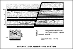
Four facies associations were defined:
- Alluvial braided river, comprising stacked units of fine to coarse-grained, poorly sorted, cross-bedded sandstone. There are no shales present to act as permeability barriers to vertical flow. Excellent sweep could result from a wide well spacing in these rocks. However, there may be preferential flow through the coarser base of the sandstones, and the flood front could be unstable at the laminar scale as a result of grain size variation in the cross-beds.
- Delta plain characterized by multistory sandstone channels and laterally extensive delta-plain siltstones. The bases of the channels commonly show silty conglomerate lags that are likely flow barriers or baffles. The persistent, thick siltstone intervals impart a strong degree of flow layering and create several stacked hydraulic units within this facies association.
- Proximal delta front (Figure 8). This comprises a series of thick mouth-bar sandstones and channel systems separated by extensive delta-front siltstones and mudstones. The latter can potentially form permeability barriers and create stacked hydraulic units.
- Distal delta front. This facies association comprises interbedded thin fine-grained sandstone, siltstone, and mudstone beds. The thin sandstones are extensive, highly layered, and have low permeability.
Sweep patterns in deltaic sandstone reservoirs
Deltas comprise stratigraphically complex jigsaw-puzzle and labyrinth reservoirs with significant potential for bypassed oil. Tyler et al.[24] commented on the recovery efficiencies of the various types of delta systems in Texas. Fluvial-dominated reservoirs show low to average recoveries because of the predominance of fluvial channels and an overall labyrinthine geometry. Wave-dominated deltas show more lateral continuity and have significantly higher recoveries. They commonly have large aquifers, and as a result these reservoirs will be supported by strong water drives.
Tyler and Ambrose[25] described the sweep patterns in a wave-dominated delta system from the Cayce reservoir of the North Markham-North Bay City field in Texas. Two distinct patterns occur. Water flows preferentially along fluvial channels. The beach ridge, delta front, and shoreface sandstones are more laterally continuous and show broader zones of edge-water influx.
Sweep patterns in distributary channels
Distributary channels tend to be narrow with a common width range of 10–300 m (33–984 ft).[8] It is possible that hydrocarbons in isolated distributary channels may be missed in fields with larger well spacings. Richardson et al.[13] stated that it could be impractical to try and locate both injection and production wells to sweep individual distributary channels. The sweep efficiency in the distributary channels will be low without direct injection support, particularly if the sand bodies are isolated. There is a better chance of improving recovery by waterflooding the delta-front sandstones.
Sweep patterns in delta-front sediments
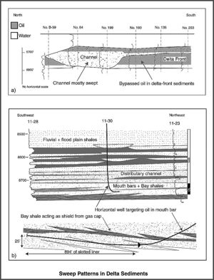
Sneider et al.[9] showed how considerable flow complexity can be present in the delta-front environment. This results from the incision of fining-upward channels into coarsening-up mouth bars. The coarser basal sections of the channels act as permeability fairways for water ingress to production wells with the potential to leave oil bypassed within the finer grained parts of the mouth bars. Similar sweep patterns were noted by Hartman and Paynter[26] in Tertiary fluviodeltaic sandstones in fields offshore of Louisiana (Figure 9a).
Swanson[27] noted that distributary channels tended to be more productive than mouth bars in the Mississippian upper Morrow Sandstone of the Anadarko Basin, United States. The basal sections of the distributary channels appear to be well connected, whereas the extremely laminated lower parts of the upper mouth bar facies tend to restrict flow. The degree to which mudstone laminations are present in mouth bars may control the vertical sweep of these bodies.
Repeated delta lobe switching can result in a series of stacked mouth-bar intervals within a thick interval of deltaic sediments. Vertical amalgamation can produce thick multistory bodies as a result, Elsewhere, individual mouth bars can be separated vertically by bay mudstones and marine flooding events.
Hamilton et al.[7] described a wave-dominated delta reservoir in the Budare field, Venezuela. Mouth-bar facies amalgamate to produce vertical continuous sand bodies up to 27 m (90 ft) thick. These are in vertical communication. Distributary channel complexes also comprise stacked sandstone units up to 17 m (55 ft) thick and likewise show good vertical communication. By contrast, the strand-plain complexes flanking the mouth bars received only peripheral sediments separated by widespread numerous marine shales. Vertical sweep is poor in the strand-plain sandstones, and these are targets for recovering bypassed oil.
Eight delta-front cycles comprise the Miocene reservoir interval of the Peciko gas field in the Mahakam Delta, Indonesia. The cycles are predominately mouth-bar sand bodies, 30–50 m (98–164 ft) thick. They are separated by marine-shale flooding events, which act as permeability barriers. Each delta cycle represents a distinct hydraulic unit or drainage cell within the field.[28]
Tye et al.[1] found examples of mouth bars vertically separated and isolated by bay mudstones in the Ivishak Formation of the Prudhoe Bay field, Alaska. They successfully targeted bypassed oil in individual mouth bars by drilling horizontal wells (Figure 9b).
See also
- Eolian reservoirs
- Meandering fluvial reservoirs
- Braided fluvial reservoirs
- Siliciclastic shorelines and barrier island reservoirs
- Deep-water marine reservoirs
- Carbonate reservoir
References
- ↑ 1.0 1.1 1.2 1.3 1.4 1.5 1.6 Tye, R. S., J. P. Bhattacharya, J. A. Lorsong, S. T. Sindelar, D. G. Knock, D. D. Puls, and R. A. Levinson, 1999, Geology and stratigraphy of fluvio-deltaic deposits in the Ivishak Formation: Applications for development of Prudhoe Bay field, Alaska: AAPG Bulletin, v. 83, no. 10, p. 1588–1623.
- ↑ Evamy, B. D., J. Haremboure, P. Kamerling, W. A. Knaap, F. A. Molloy, and P. H. Rowlands, 1978, Hydrocarbon habitat of Tertiary Niger Delta: AAPG Bulletin, v. 62, no. 1, p. 1–39.
- ↑ Tuttle, M. L. W., R. R. Charpentier, and M. E. Brownfield, 1999, The Niger Delta petroleum system: Niger Delta Province, Nigeria, Cameroon, and Equatorial Guinea, Africa: U.S. Geological Survey Open File Report 99-501, 210 p.
- ↑ 4.0 4.1 4.2 Galloway, W. E., and D. K. Hobday, 1996, Terrigenous clastic depositional systems: Applications to petroleum, coal, and uranium exploration: New York, Springer-Verlag, 489 p.
- ↑ Galloway, W. E., 1975, Process framework for describing the morphologic and stratigraphic evolution of deltaic depositional systems, in M. L. Broussard, ed., Deltas, models for exploration: Houston Geological Society, p. 87–98.
- ↑ Coleman, J. M., and L. D. Wright, 1975, Modern river deltas: Variability of processes and sand bodies, in M. L. Broussard, ed., Deltas, models for exploration: Houston Geological Society, p. 99–149.
- ↑ 7.0 7.1 Hamilton, D. S., et al., 2002, Reactivation of mature oil fields through advanced reservoir characterization: A case history of the Budare field, Venezuela: AAPG Bulletin, v. 86, no. 7, p. 1237–1262.
- ↑ 8.0 8.1 8.2 Gibling, M. R. 2006, Width and thickness of fluvial channel bodies and valley fills in the geological record: A literature compilation and classification: Journal of Sedimentary Research, v. 76, p. 731–770.
- ↑ 9.0 9.1 9.2 Sneider, R. M., C. N. Tinker, and L. D. Meckel, 1978, Deltaic environment reservoir types and their characteristics: Journal of Petroleum Technology, v. 30, no. 11, p. 1538–1546.
- ↑ Allen, G. P., and J. L. C. Chambers, 1998, Sedimentation in the modern and Miocene Mahakam delta: Indonesian Petroleum Association, 236 p.
- ↑ 11.0 11.1 11.2 Reynolds, A. D., 1999, Dimensions of paralic sandstone bodies: AAPG Bulletin, v. 83, no. 2, p. 211–229.
- ↑ 12.0 12.1 Fisk, H. N., 1961, Bar-finger sands of the Mississippi delta, in J. A. Peterson and J. C. Osmond, eds., Geometry of sandstone bodies: AAPG Symposium, SP22, p. 29–52.
- ↑ 13.0 13.1 Richardson, J. G., J. B. Sangree, and R. M. Sneider, 1989, Sand-rich deltas: Journal of Petroleum Technology, v. 41, no. 2, p. 157–158.
- ↑ Tye, R. S., and J. J. Hickey, 2001, Permeability characterization of distributary mouth bar sandstones in Prudhoe Bay field, Alaska: How horizontal cores reduce risk in developing deltaic reservoirs: AAPG Bulletin, v. 85, no. 3, p. 459–475.
- ↑ Willis, B. J., J. P. Bhattacharya, S. L. Gabel, and C. D. White, 1999, Architecture of a tide-influenced delta in the Frontier Formation of central Wyoming: Sedimentology, v. 46, no. 4, p. 667–688.
- ↑ Weber, K. J., 1982, Influence of common sedimentary structures on fluid flow in reservoir models: Journal of Petroleum Technology, v. 34, no. 3, SPE Paper 9247, p. 655–672.
- ↑ Bhattacharya, J. P., and R. G. Walker, 1992, Deltas, in R. G. Walker and N. P. James, eds., Facies models response to sea level change: Geological Association of Canada, 2d edition, p. 157–177.
- ↑ Sibley, D. M., and S. S. Mastoris, 1994, Rethinking conventional field development: 3-D shows direct detection of bypassed oil reserves: Presented at the International Petroleum Conference and Exhibition of Mexico, Society of Petroleum Engineers, October 10–13, 1994, Veracruz, Mexico, SPE Paper 28719, 11 p.
- ↑ Hart, B. S., D. M. Sibley, and P. B. Flemings, 1997, Seismic stratigraphy, facies architecture and reservoir character of a Pleistocene shelf-margin delta complex, Eugene Island Block 330 field, offshore Louisiana: AAPG Bulletin, v. 81, no. 3, p. 380–397.
- ↑ Ainsworth, R. B., M. Sanlung, and S. T. C. Duivenvoorden, 1999, Correlation techniques, perforation strategies, and recovery factors: An integrated 3-D reservoir modeling study, Sirikit field, Thailand: AAPG Bulletin, v. 83, no. 10, p. 1535–1551.
- ↑ Dreyer, T., 1993, Geometry and facies of large-scale flow units in fluvial-dominated fan-delta-front sequences, in M. Ashton, ed., Advances in reservoir geology: Geological Society Special Publication 69, p. 135–174.
- ↑ McPherson, J. G., G. Shanmugan, and R. J. Moiola, 1988, Fan deltas and braid deltas: Conceptual problems, in W. Nemec and R. J. Steel, eds., Fan deltas: Sedimentology and tectonic settings: Glasgow, Blackie and Son, p. 14–22.
- ↑ 23.0 23.1 Reynolds, A. D., et al., 1998, Implications of outcrop geology for reservoirs in the Neogene productive series: Apsheron Peninsula, Azerbaijan: AAPG Bulletin, v. 82, no. 1, p. 25–29.
- ↑ Tyler, N., J. Crispin Gholston, and W. A. Ambrose, 1987, Oil recovery in a low-permeability, wave-dominated, Cretaceous, deltaic reservoir, Big Wells (San Miguel field, South Texas): AAPG Bulletin, v. 71, no. 10, p. 1171–1195.
- ↑ Tyler, N., and W. A. Ambrose, 1986, Facies architecture and production characteristics of strand-plain reservoirs in North Markham-North Bay City field, Frio Formation, Texas: AAPG Bulletin, v. 70, no. 7, p. 809–829.
- ↑ 26.0 26.1 Hartman, J. A., and D. D. Paynter, 1979, Drainage anomalies in Gulf Coast Tertiary sandstones: Journal of Petroleum Technology, SPE Paper 7532, v. 31, no. 10, p. 1313–1322.
- ↑ Swanson, D. C., 1979, Deltaic deposits in the Pennsylvanian upper Morrow Formation of the Anadarko Basin: Tulsa Geological Society Special Publication 1, p. 115–168.
- ↑ Lambert, B., B. C. Duval, Y. Grosjean, I. M. Umar, and P. Zaugg, 2003, The Peciko case history: Impact of an evolving geologic model on the dramatic increase in reserves in the Mahakam delta, in M. T. Halbouty, ed., Giant oil and gas fields of the decade 1990–1999: AAPG Memoir 78, p. 297–320.
