Seismic facies analysis
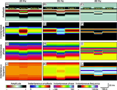
Seismic facies are "mappable, three dimensional seismic units composed of groups of reflections whose parameters differ from those of adjacent facies units”.[1] Seismic facies analysis is the description and interpretation of seismic reflection parameters, such as configuration, continuity, amplitude, and frequency, within the stratigraphic framework of a depositional sequence. Its purpose is to determine all variations of seismic parameters within third-order sequences and their systems tracts in order to determine lateral lithofacies and fluid type changes.[2]

Reflection parameters
There are five useful reflection parameters:
- Configuration (reflection geometry)
- Continuity
- Amplitude
- Frequency
- Interval velocity
Depositional environment, sediment source, and lithofacies can be interpreted by grouping these parameters into mappable, three-dimensional seismic facies.[4] The table below[1] summarizes the information obtained from each parameter.
| Reflection parameter | Geologic interpretation |
|---|---|
| Configuration |
|
| Continuity |
|
| Amplitude |
|
| Frequency |
|
| Interval velocity |
|
Seismic facies analysis procedure
The table below outlines a procedure to analyze seismic facies from a grid of sections (vertical) of 2-D or 3-D seismic data (modified from [1]).
| Step | Action |
|---|---|
| 1 | Divide each depositional sequence into seismic facies units on all seismic sections. |
| 2 | Describe the internal reflection configuration and terminations of each seismic facies unit, i.e., sigmoid, parallel, downlap. |
| 3 | Transfer seismic facies descriptions from seismic sections to a shot point map of each sequence. |
| 4 | Combine seismic facies distribution and thickness with the map distribution of any other diagnostic parameters, such as interval velocity or localized amplitude anomalies. |
| 5 | Integrate well and outcrop data with seismic facies distribution. |
| 6 | Interpret the seismic facies maps in terms of depositional settings such as marine or nonmarine, water depth, basin position, energy, transport direction, or any other depositional aspects. |
| 7 | Estimate lithology using depositional setting interpretation from step 6 and all available data. |
See also
References
- ↑ 1.0 1.1 1.2 Mitchum, R., M., Vail, P., R., Sangree, J., B., 1977, Seismic stratigraphy and global changes in sea level, part 6: stratigraphic interpretations of seismic reflection patterns in depositional sequences, in Payton, C., E., ed., Seismic Stratigraphy and Applications to Hydrocarbon Exploration: AAPG Memoir 26, p. 117–133.
- ↑ Vail, P., R., 1987, Seismic stratigraphy interpretation procedure, in Bally, A., W., ed., Atlas of Seismic Stratigraphy: AAPG Studies in Geology No. 27, p. 2.
- ↑ Zeng, Hongliu, 2013, Frequency-dependent seismic-stratigraphic and facies interpretation: AAPG Bulletin, v. 97, no. 2, p. 201–221, DOI:10.1306/06011212029.
- ↑ Bally, A., W., ed., 1987, Atlas of Seismic Stratigraphy: AAPG Studies in Geology 27, vol. 1, 124 p.