Surface production equipment
| Development Geology Reference Manual | |

| |
| Series | Methods in Exploration |
|---|---|
| Part | Production engineering methods |
| Chapter | Surface production equipment |
| Author | James Jennings |
| Link | Web page |
| Store | AAPG Store |

There are three major components of surface production equipment:
- Wellhead
- Separators and heater treaters
- Tank batteries and meter facilities
Production engineers often design all equipment on the lease. After the oil and gas leaves the lease, pipeline or facilities engineers take over.
Wellhead[edit]
The wellhead is the equipment at the surface that provides support for the tubulars inside the well, a pressure seal between the tubulars, and a means of controlling production from the well. Typically, the wellhead consists of a casing head for each casing string, a tubing head, and a Christmas tree. For each string of pipe in the well, casing, or tubing, some means of support and pressure sealing must be provided. This is the function of the casing and tubing heads. The Christmas tree provides the necessary valving and chokes to control the production from a well capable of flowing. For a well that is being pumped, the Christmas tree is replaced by wellhead equipment that accommodates the pumping operation.
Figure 1 shows a typical wellhead for a flowing well. Notice that a choke is provided to control the rate of production from the well in addition to the tubing wing valve, which provides for a complete shut-off of the production. The choke can be either fixed or variable in size. The choke is nothing more than a small orifice, usually from 1/8 to 3/4 in. in diameter, that restricts the flow rate.

Other valves are present on the side of the wellhead. These are called casing valves and they provide access to the various annulii between casing strings and tubing. Normally, the wellhead is fitted with pressure gauges for monitoring pressure within the different annulii and in the tubing.
The flow rate from either an oil well or a gas well can be easily estimated from the wellhead pressure if the wellhead pressure is at least twice the flowline pressure. For an oil well, the Gilbert equation is commonly used:

where
- q = gross liquid flow rate (bbl/day)
- Ptf = flowing tubing head pressure (psia)
- R = gas to liquid ratio (MSCF/bbl)
- S = choke size (1/64 in.)
For a gas well, the following equation is used:

where
- q = gas flow rate (MSCF/day)
- Ptf = flowing tubing head pressure (psia)
- d = choke size (in.)
- G = gas specific gravity
- T = wellhead temperature (°R)
Separators and heater treaters[edit]
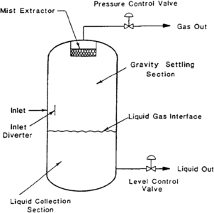
Figure 2 Vertical separator.
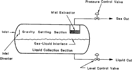
Figure 3 Horizontal separator.
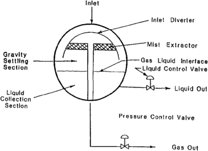
Figure 4 Spherical separator.
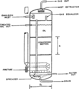
Figure 5 Vertical heater treater.


Once liquids are brought to the surface, the oil, gas, and water must be separated for ease of measurement and transportation. A separator is a vessel used to separate liquid from gas. In some cases, the liquid may be additionally separated into individual oil and water streams. A separator is commonly given any of the following names:
- Gun barrel
- Free water knock out
- Knock out
- Trap
- Scrubber
- Stage separator
A heater treater is simply a separator that is designed to separate primarily oil from water. Heating of the mixture normally speeds up and improves the separation process.
Several physical processes are commonly used in the separation process:
- Gravity settling
- Centrifugal force
- Impingement
- Electrostatic precipitation
- Filtration
- Heat
The design of a particular separator depends on the nature of the flow stream to be separated. For a gas well, the separator usually separates a small amount of liquid from the gas. In an oil well, the separation may involve a small amount of gas for the amount of liquid. In general, the well stream separator must separate the mostly liquid fluids from the mostly gas fluids. In addition, it must separate liquid hydrocarbon from liquid water and remove most of the entrained liquid mist from the gas.
To accomplish the separation, the separator is usually designed to control and dissipate the well stream flowing energy. Once gas and liquid velocities are slow enough, gravity causes the liquid to settle and the gas to rise. The size of the vessel must be such that adequate time is allowed for this settling to occur before the fluid leaves the separator. If water is to be separated from oil, then the liquid residence time depends on the volume of the fluid being handled and the specific gravity of the two liquids. Many times, a mist extractor composed of vanes, mesh pads, or a cyclonic passage is used to remove residual liquid droplets from the gas stream.
There are three types of separators: vertical (Figure 2), horizontal (Figure 3), and spherical (Figure 4). Horizontal separators are found in both the single tube and double tube design. Advantages of the vertical separator include
- Good for predominantly liquid streams
- Can handle producing stream surges without carryover
- Occupies little space (small footprint)
- Easily cleaned of sand and mud
Advantages of the horizontal separator are
- Good for predominantly gas streams
- Easy to fabricate, ship, and install
- Low profile
And for the spherical separator, the advantages are
- Good for high pressure gas wells
- Compact, small size
Figure 5 shows a typical vertical heater treater. Notice that a heater treater is simply a separator in which a firetube has been placed to heat the liquid mixture as it enters the vessel. This heating of the oil and water mixture reduces the viscosity and promotes the separation of the two phases. The fuel for the firetube is usually taken from the gas produced from the well.
Tank batteries and metering[edit]

Tanks must be provided to hold both oil and water for shipping or disposal. Usually, at least two oil tanks are used, one for shipping and one for filling. The volume of oil being shipped is sometimes determined by simply measuring the height of the fluid in the tank, or “strapping” the tank. Many of the more modern production facilities have lease automatic custody transfer (LACT) units installed. These stations continuously measure the flow into the shipping point and periodically sample the product being shipped so that oil gravity, temperature, pressure, and water content are known. The metering in this case is done with a positive displacement meter.
The measurement of gas is usually done with an orifice meter. Figure 6 shows such an installation. For a given meter installation, the gas flow rate depends on the pressure on both sides of the orifice and the temperature of the gas. These pressures and temperatures are normally recorded on a circular chart. This chart is later used to determine the total gas flow over a particular time period. Many installations today have digital flow calculating and recording devices installed at the meter. These installations have proven to be accurate, and they provide for the telemetering of the flow information from a remote installation.
See also[edit]
- Production testing
- Production histories
- Artificial lift
- Stimulation
- Introduction to production engineering methods
- Pressure transient testing
- Well completions
- Production logging
- Production problems
- Workovers
External links[edit]
| find literature about Surface production equipment |