Predicting reservoir drive mechanism
| Exploring for Oil and Gas Traps | |

| |
| Series | Treatise in Petroleum Geology |
|---|---|
| Part | Predicting the occurrence of oil and gas traps |
| Chapter | Predicting reservoir system quality and performance |
| Author | Dan J. Hartmann, Edward A. Beaumont |
| Link | Web page |
| Store | AAPG Store |
One can predict drive type by analyzing (1) the reservoir system of a prospect and (2) the production history characteristics of similar nearby reservoirs.
Predicting drive type[edit]
Reservoir analysis includes making cross sections, structural maps, and isopach maps. Analyzing nearby producing fields yields the best set of inferential data. This includes (1) making plots of historical oil, gas, condensate, and water production and pressure decline and (2) making cumulative production maps. When all available information has been assembled, find the drive type that best fits the prospective reservoir system. The table below summarizes typical characteristics of primary drive types.
| Drive | Characteristics |
|---|---|
| Water |
|
| Gas expansion |
|
| Solution gas |
|
| Rock drive |
|
| Gravity |
|
Production history characteristics for drives[edit]

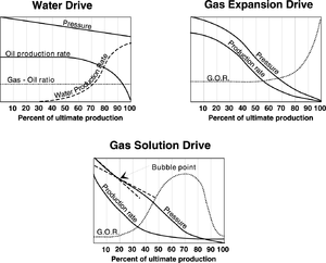
Figure 1 shows oil reservoir production history characteristics for water, gas expansion, and gas solution drives. To predict reservoir drive type, if possible, plot the production history of nearby fields with analogous reservoir systems and compare with these graphs.
Recoveries of oil vs. gas reservoirs[edit]
The table below shows typical recovery rates for oil vs. gas reservoir systems for different reservoir drive mechanisms with mega and macro port type systems.[2][3] Recoveries would be lower for meso to micro port systems. Use this table to project the recoveries for your prospects.
| Reservoir drive mechanism | Percent ultimate recovery | |
|---|---|---|
| Gas | Oil | |
| Strong water | 30–40 | 45–60 |
| Partial water | 40–50 | 30–45 |
| Gas expansion | 50–70 | 20–30 |
| Solution gas | N/A | 15–25 |
| Rock | 60–80 | 10–60 |
| Gravity drainage | N/A | 50–70 |
Recoveries for sandstone vs. carbonate reservoirs[edit]
The American Petroleum Institute conducted a study to determine recovery amounts and efficiencies for water vs. solution gas drives for sandstone and carbonate reservoirs, summarized in the table below.[4] Use the table to project recoveries for your prospects.
| Drive | Units | Sandstone | Carbonate | ||||
|---|---|---|---|---|---|---|---|
| Min. | Ave. | Max. | Min. | Ave. | Max. | ||
| Water | bbl/acre-ft | 155 | 571 | 1,641 | 6 | 172 | 1,422 |
| m3/h-m | 199 | 735 | 2,113 | 8 | 221 | 1,831 | |
| % STOOIP | 28 | 51 | 87 | 6 | 44 | 80 | |
| Solution gas | bbl/acre-ft | 47 | 154 | 534 | 20 | 88 | 187 |
| m3/h-m | 60 | 198 | 688 | 26 | 113 | 241 | |
| % STOOIP | 9 | 21 | 46 | 15 | 18 | 21 | |
See also[edit]
- Reservoir system
- Analyzing a reservoir system
- Defining flow units and containers
- Reservoir drive mechanisms
References[edit]
- ↑ Levorsen, A. I., 1954, Geology of Petroleum: San Francisco, W. H. Freeman, 703 p.
- ↑ Farina, J. personal communication, 1998
- ↑ Garb, F. A., and G. L. Smith, 1987, Estimation of oil and gas reserves, in H. B. Bradley, ed., Petroleum Engineering Handbook: SPE, p. 40-1–40-32.
- ↑ Arps, J. J., 1964, Engineering concepts useful in oil finding: AAPG Bulletin, v. 48, no. 2, p. 943-961.