Difference between revisions of "Production problems"
Cwhitehurst (talk | contribs) |
|||
| Line 23: | Line 23: | ||
To minimize the production of unwanted gas or water, flow rates from the well must be maintained so that the pressure gradients around the wellbore will not cone in the unwanted fluids. Flow performance calculations or reservoir models can be used to help predict the optimum production rates. However, because of pressure depletion within the oil zone, a pressure differential will eventually develop between the water and/or gas zones, such that encroachment will eventually occur. After this point, the well may soon become uneconomical due to the production of these unwanted fluids. | To minimize the production of unwanted gas or water, flow rates from the well must be maintained so that the pressure gradients around the wellbore will not cone in the unwanted fluids. Flow performance calculations or reservoir models can be used to help predict the optimum production rates. However, because of pressure depletion within the oil zone, a pressure differential will eventually develop between the water and/or gas zones, such that encroachment will eventually occur. After this point, the well may soon become uneconomical due to the production of these unwanted fluids. | ||
| − | Several authors have studied these types of reservoirs to determine which production methods result in the maximum amount of produced oil. | + | Several authors have studied these types of reservoirs to determine which production methods result in the maximum amount of produced oil. [Byrne and Morse<ref name=Byrne_and_Morse_1973>Byrne, W. B., Jr., and R. A. Morse, Water coning may not be harmful—Part 1: The Oil and Gas Journal, September 3, p. 66-70.</ref> evaluated various reservoir and completion scenarios and determined that increasing the well penetration and increasing the pressure drawdown at the producing well would result in an increase in the water-oil ratio. However, there was a corresponding increase in the oil production of the same order of magnitude. Their results showed no indication that ultimate recovery was adversely affected by the increased producing rates. |
==Near wellbore restrictions== | ==Near wellbore restrictions== | ||
Revision as of 20:08, 17 January 2014
| Development Geology Reference Manual | |

| |
| Series | Methods in Exploration |
|---|---|
| Part | Production engineering methods |
| Chapter | Production problems |
| Author | Bradley M. Robinson |
| Link | Web page |
| Store | AAPG Store |
The production of oil or gas from underground reservoirs involves chemical and mechanical processes that affect the wellbore. Many of these processes can eventually cause a problem with the well, resulting either in a decrease in production or in failure of equipment installed downhole or at the surface. Most of the serious problems can be avoided or delayed through preventive maintenance techniques or early recognition from regular analysis of producing rates, fluids, and the mechanical condition of the well. Such practices can prevent a costly workover that may be required to restore production from the well and may also prevent total loss of the wellbore.
Water-gas coning
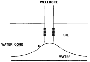
When water underlies an oil column or a gas cap exists above, the phenomenon of coning can occur when the oil is produced. Muskat[1] noted that coning is most likely to occur when a wellbore only penetrates a portion of the formation or when the perforations are placed only in the oil zone (Figure 1). The horizontal and vertical pressure gradients created by the production of oil causes a deformation of the oil-water (or oil-gas) contact. When the vertical pressure gradient exceeds the hydrostatic gradient down to the water zone, the water is pulled toward the well, resulting in a cone-shaped distortion of the oil-water contact. If a well is produced too hard, water breakthrough can occur. The same basic principles apply to the downward coning of gas from a gas cap.
To minimize the production of unwanted gas or water, flow rates from the well must be maintained so that the pressure gradients around the wellbore will not cone in the unwanted fluids. Flow performance calculations or reservoir models can be used to help predict the optimum production rates. However, because of pressure depletion within the oil zone, a pressure differential will eventually develop between the water and/or gas zones, such that encroachment will eventually occur. After this point, the well may soon become uneconomical due to the production of these unwanted fluids.
Several authors have studied these types of reservoirs to determine which production methods result in the maximum amount of produced oil. [Byrne and Morse[2] evaluated various reservoir and completion scenarios and determined that increasing the well penetration and increasing the pressure drawdown at the producing well would result in an increase in the water-oil ratio. However, there was a corresponding increase in the oil production of the same order of magnitude. Their results showed no indication that ultimate recovery was adversely affected by the increased producing rates.
Near wellbore restrictions
Restrictions can occur in the formation or within the wellbore that can cause a decrease in oil or gas production. These restrictions are a result of changes in the formation or fluid properties around the wellbore, chemical reactions within the formation or the wellbore, mechanical problems, or inadequate completion techniques.
Partial penetration
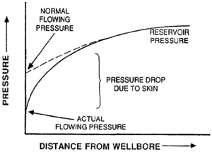
If only a portion of the productive formation has been drilled or perforated, this is referred to as partial penetration. Gas or oil that is flowing from the reservoir to this limited area will cause large pressure gradients near the wellbore. Fluid flow within the pores may also reach turbulent velocity, thus generating additional pressure drop and reducing the productivity of the well. Studies by Harris[3] and Odeh[4] on partial penetration have concluded that the effects are similar to skin damage around the wellbore (that is, an altered permeability that is lower than the reservoir permeability). To overcome these effects, the well must be deepened to expose all of the productive interval or more perforations must be added to expose additional reservoir to flow. Figure 2 illustrates the effects of partial penetration on pressure drop around the wellbore.
Scales and precipitates
Plugged or inadequate perforations have the same effect as partial penetration; that is, reservoir fluids are restricted from flowing into the wellbore. Perforations can become plugged with scale or other solid particles that are precipitated from formation fluids (see “Rock-Water Interactions: Formation Damage”). As these fluids are produced, equilibrium conditions of pressure and temperature become altered (especially near the wellbore) causing precipitation of these particles. Some precipitates can form when incompatible fluids come in contact downhole. Workover and completion fluids should be tested with formation fluids for compatibility. Precipitates can also occur in a formation after an acid treatment.
The most common types of scale are calcium carbonate and calcium sulfate (gypsum). Sodium chloride (salt), sulfur, and other minerals can also be precipitated under certain conditions. The formation of these scales or solids can be minimized or prevented through use of chemical inhibitors, provided the produced fluids are analyzed ahead of time. If not, it may be necessary to perform a workover to clean out the well.
Paraffin or asphaltenes
Some oils can precipitate appreciable amounts of paraffin or asphaltenes as the temperature and pressure are reduced in the near wellbore region. Most often these deposits form near the surface where the temperature is lowest. However, there have been many confirmed cases of paraffin buildup near the perforations. Removal of these deposits can be accomplished with heated oil or chemical solvents.
Decrease in relative permeability
As the well is produced, the lowest pressures are observed near the wellbore. In oil reservoirs, this pressure drop can result in the release of gas. Similarly, in a gas reservoir, the lower pressure can result in the formation of condensate fluids around the wellbore. The increase in saturation of a second phase of fluid decreases the permeability to flow of the primary fluid. The ability of these different fluids to flow is defined by the relative permeability characteristics of the rock and the fluids. To reduce this problem, a method must be implemented, such as hydraulic fracturing, to help decrease the pressure drop around the wellbore (see “Stimulation”). Eventually, pressure will deplete further out in the reservoir and the flow capacity of the primary fluid will be reduced.
Emulsions
Emulsions can also form in or around the wellbore and may create a block that restricts or completely cuts off production from the reservoir. An emulsion is simply a mixture of one liquid (the discontinuous phase) that is dispersed within another liquid (the continuous phase) and is likely to be formed when oil and water are mixed. Stable emulsions are the most likely to block production and are also the most difficult to remove. For an emulsion to become stable, an emulsifying agent (fine particles and/or surfactants) must be present. Although surfactants can cause emulsions, other surfactants at the proper concentrations can break emulsions. Also, special deemulsifier agents are available to remove emulsion blocks.
Formation collapse
In loosely consolidated or weakly cemented formations, the severe pressure drop that occurs around a wellbore can cause the formation to collapse. When this occurs, the pore structure is altered and the permeability is reduced, causing skin damage around the wellbore. To prevent this, a small hydraulic fracture treatment can be performed early in the life of the well. The fracture treatment will help minimize the pressure gradients and reduce the chance of formation collapse around the wellbore.
As the pressure is depleted throughout the reservoir, the overburden pressure caused by the overlying rock tends to compress the formation. This overburden pressure can also alter the pore structure and reduce the permeability. The degree of severity is a function of the formation compressibility. Soft formations, such as those found in the Gulf Coast, can experience reductions in permeability by a factor of 10 or greater. More competent sandstones or carbonate reservoirs may only experience a small reduction in permeability. These effects must be taken into account when predicting long-term performance; otherwise, predictions will be too optimistic.
Corrosion
The potential for corrosion must be recognized and diagnosed early in the producing life of a field. Otherwise, expensive workovers and repairs may be necessary. Corrosion within the wellbore can occur in various forms and is often accompanied by the formation of scale (discussed previously). Corrosion can be divided into three categories:
- Oxidation
- Electrical corrosion
- Chemical corrosion
Oxidation is essentially the exposure of metal to oxygen primarily from air, but it can also be obtained from oxygen in produced formation water. The result is the formation of rust on the rubulars in the wellbore. Prevention of rust can be accomplished through the use of special resistant alloys in the rubulars, chemical inhibitors, and cathodic protection.
Electrical corrosion is caused by the natural flow of an electrical current from the metal pipe (anode) into the formation (electrolyte) or into another metal that is lower in the electromotive series (cathode). As current flows, the anode will corrode. To prevent this type of corrosion, the expected anode can be insulated or coated. Cathodic protection can also be installed to slow down the flow of current.
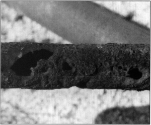
Chemical corrosion is caused by soluble organic acids within the produced formation water or carbon dioxide within gas in the reservoir. These agents react with the metal and cause severe pitting (Figure 3). The incidence and severity of this type of corrosion is increased with higher bottomhole temperatures.
Another form of corrosion is that from hydrogen sulfide (H2S), which is a combination of electrical and chemical corrosion. The severity and potential danger of this type of corrosion makes it worth special mention (see “Wellsite safety”). Hydrogen sulfide causes damage to rubulars by several different mechanisms. First, a sulfide scale forms and causes pitting as the steel acts as an anode and transmits current to the sulfide scale. As a result of formation of the sulfide scale, hydrogen is liberated, which is absorbed by the steel. The hydrogen combines with the carbon compounds in the steel, reducing its strength and causing it to blister and crack. Since hydrogen sulfide is a poisonous gas, its production should be considered dangerous because of the potential for damage to surface and downhole equipment. Special corrosion inhibitors are commercially available to help protect the metal equipment from these types of corrosion.
Liquid loading
Liquid that enters the wellbore at the bottom of the hole can only flow to the surface if the difference in pressure between the bottom and the top of the well is greater than the hydrostatic pressure of the fluid column, plus any friction that occurs as a result of flow up the tubing. If the pressure is not sufficient, the fluid will remain static in the wellbore. This is referred to as liquid loading. If gas is primarily being produced, water flowing from the formation, or condensed within the tubing, can also accumulate in the wellbore if the gas is not flowing at sufficient velocity to lift the water from the well. Accumulation of this static fluid column can impose an additional backpressure on the formation that can significantly reduce the productivity of the well or can actually “kill” the well so that it does not flow at all.
When liquid loading occurs, it may be necessary to change the wellbore configuration or to install artificial lift equipment. For example, the size of the tubing affects the velocity of the fluid flowing up the well. If smaller tubing is used, the velocity of the fluid will be greater because of the smaller cross-sectional area. From a study of over 100 flowing gas wells, Turner et al.[5] developed a useful correlation to determine the minimum flow rate (and thus, velocity) required to lift liquids continuously from a gas well. Turner's correlation can be used to determine the size tubing required to remove water continuously from a well that is flowing at a specific rate.
In oil or gas wells that make large volumes of water or condensate, it may be necessary to install artificial lift equipment to pump the liquids to the surface. Most common methods of artificial lift include rod pumps, submersible pumps, and gas lift valves (see “Artificial lift”).
Mechanical failures
Mechanical failures can occur in a well for a variety of reasons. They are usually related to one of the following: (1) the corrosion of downhole equipment, (2) the collection of debris or scale in the wellbore, (3) the production of formation sand or collapse of the formation, (4) insufficient cement protection, or (5) the use of equipment that is not designed to withstand the depth, temperature, or pressure of a well.
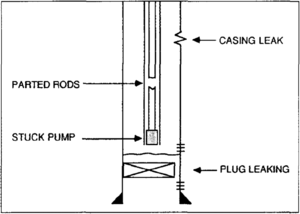
The type of equipment normally prone to such failure is the tubing, casing, rod string, downhole pumps, packers, gas lift valves, and plugs in the well bore (Figure 4). After long-term exposure to downhole conditions, breakage or wear can occur in any of this equipment. Extensive workovers (specifically, fishing operations) can be prevented by regular maintenance of the downhole equipment (see “Workovers”). A proper maintenance schedule can be established for any field once one has properly analyzed the produced fluids and conditions of the reservoir.
Specific diagnostic techniques can be applied in an effort to determine where a failure has occurred. For example, a casing leak can be detected by running a packer in the well and pressure testing the casing at various intervals in the hole. Problems with rod pumping equipment can be diagnosed through the use of an instrument called a dynamometer. This instrument analyzes the strain on the polish rod at the surface as the pump goes through an upstroke and downstroke cycle. Other diagnostic methods are available, and in some instances, it may be necessary to perform several tests before mechanical problems can be pinpointed.
See also
- Production testing
- Production histories
- Artificial lift
- Surface production equipment
- Stimulation
- Introduction to production engineering methods
- Pressure transient testing
- Well completions
- Production logging
- Workovers
References
- ↑ Muskat, M., 1949, Physical principles of oil production: New York, McGraw-Hill, chap. 5.
- ↑ Byrne, W. B., Jr., and R. A. Morse, Water coning may not be harmful—Part 1: The Oil and Gas Journal, September 3, p. 66-70.
- ↑ Harris, M. H., 1966, The effect of perforating on well productivity: Journal of Petroleum Technology, April, p. 518.
- ↑ Odeh, A. S., 1968, Steady-state flow capacity of wells with limited entry to flow: Society of Petroleum Engineers Journal, March, p. 43.
- ↑ Turner, R. G., Hubbard, M. G., Pukler, A. E., 1969, Analysis and prediction of minimum flow rate for the continuous removal of liquids from gas wells: Journal of Petroleum Technology, Nov., p. 1475–1482.


