Thelma field
| Rift-Related Coarse-Grained Submarine Fan Reservoirs: The Brae Play, South Viking Graben, North Sea | |
| |
| Series | Memoir |
|---|---|
| Chapter | A Depositional Model for the T-Block Thelma Field, UKCS Block 16/17 |
| Author | Mark A. Jones, Bryan T. Cronin, Simon Allerton |
| Link | Web page |
| Store | AAPG Store |
Introduction[edit]
Block 16/17 (T-Block) is located in the U.K. sector of the South Viking Graben (SVG) adjacent to the Fladen Ground Spur (Figure 1). The T-Block fields were discovered by Philips Petroleum in the 1970s and have been on production since 1996. Three oil fields in the block produce from the Upper Jurassic Brae member of the Kimmeridge Clay Formation (Tiffany, Toni, and Thelma), the most southerly of which is the Thelma field (Figure 1B), which is developed through a seabed manifold tied back to the Tiffany platform. A total of seven producers have been drilled across the whole Thelma field area (Figure 2), with four wells dominating production: C1Z, C2, C3Z, and C4, cumulatively producing more than 58 MMSTB (2014). Apart from a small-scale water injection trial at C8Y (originally a producer), there has been no water injection to date.
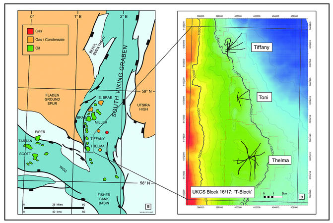
Figure 1 T-Block location map (only development wells are shown on Figure 1B).
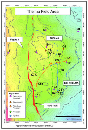
Figure 2 Thelma area: Base Cretaceous-depth structure map.


Some previous workers (Arduini et al., 1993[1]; Cherry, 1993[2]; Kerlogue et al., 1994[3]; Gambaro and Donagemma, 2003[4]) have described aspects of the structure, stratigraphy, and sedimentology of the Brae member in T-Block. Cherry (1993[2]) provides a facies and facies association scheme for the Upper Jurassic of T-Block (building on earlier work by Turner et al., 1987[5]) and discusses the interplay between structure and lithofacies distribution. He interprets depositional subenvironments and fan evolution through time, but a detailed deposition model was not proposed for any of the fields. Gambaro and Donagemma (2003[4]) describe in more detail the Thelma area stratigraphy and the derivation of key petrophysical parameters, but again, a detailed depositional model is not proposed.
The definition of a coherent depositional model for the Upper Jurassic reservoirs within the Thelma area is compromised by subsurface data quality. Mapping facies distributions has been hindered by poor-quality seismic data combined with ambiguities in the geological data (e.g., biostratigraphy). In the full paper associated with this Wiki article, this uncertainty has been addressed through a multiple deterministic scenario approach that does not anchor the interpreter to one concept, but allows several concepts to be recognized (Bentley and Smith, 2008[6]). The objective of the full paper associated with this Wiki article is to present some generalized depositional concepts for the Thelma area and critically examine them in terms of both static and dynamic data, particularly with respect to reservoir distribution and connectivity, two of the principal risk elements of this field. Detailed facies schemes have been adequately described by previous authors and will not be repeated here. Instead, the full paper associated with this Wiki article focuses more on how the integration of a range of subsurface data, both static and dynamic, has led to the recognition of three different depositional model scenarios.

Brae play[edit]
A summary of the SVG “Brae Play” is illustrated in Figure 3 to provide a context for the Thelma area. The Brae Play in the SVG is developed in the hanging wall of a major Late Jurassic rift fault system. Major footwall uplift during rifting resulted in exposure and erosion of the Fladen Ground Spur that in turn resulted in the supply of clastic sediment to the Brae Play fairway through a series of feeder systems (Harris and Fowler, 1987[8]; Fraser et al., 2003[7]). Anoxia that developed in the adjacent, restricted marine basins resulted in the deposition of organic-rich shales (the Kimmeridge Clay Formation), which act as both seal and principal source rock to the Brae Play. The Brae trend itself comprises a series of relatively small point-sourced, synrift slope apron fans that extend for approximately 100 km (60 mi) along the western flank of the SVG. A wide range of facies reflects a spectrum of gravity flow processes active at this time, and rapid lateral facies changes in both dip and strike directions are common. Typically, thick intervals of conglomerate characterize proximal fan areas adjacent to the boundary fault system, which pass basinward into sandstone-dominated turbidites and basinal mudstones, while off-axis mudstone facies provide lateral separation between the individual fans.
Structure and stratigraphy[edit]
At the Base Cretaceous unconformity (BCU), the field is evident as a dip-closed structure (Figure 2). In common with other fields in T-Block, the trap largely developed as a hanging wall inversion structure during the Cretaceous (Allerton et al., 2018[9]), with elements of both structural and stratigraphic closure to the northeast and southeast. As the oil column (471 ft [ 144 m]) exceeds the independent structural closure (275 ft [84 m]), trapping must rely on a faulted contact (or shale out) with impermeable pre-Jurassic rocks in thefootwall for the updip seal, or a sealing fault (Figure 4; Kerlogue et al., 1994[3]). The reservoir is essentially a deep-marine fan complex dominated by conglomerates, sandstones, and thin-bedded turbidites. Within the trap there are two principal reservoir units; the late Oxfordian to early Volgian Brae member and the “latest” early to middle–late Volgian sand–shale member (Figure 5). Both members represent regressive fan outbuildings during an overall sea-level rise through the Late Jurassic. They are separated vertically by the “late” early Volgian “Longicornis shale” (J66A MFS), which is a proven intraformational seal within parts of the field area and represents a temporary abandonment with cessation of coarse-clastic input into the Thelma fan system. The overlying late Volgian to Ryazanian hot shale represents final abandonment of the fan system and, in conjunction with Lower Cretaceous shales, provides the ultimate top seal and principal source rock. Middle Jurassic coals and organic shales may be secondary source rocks.
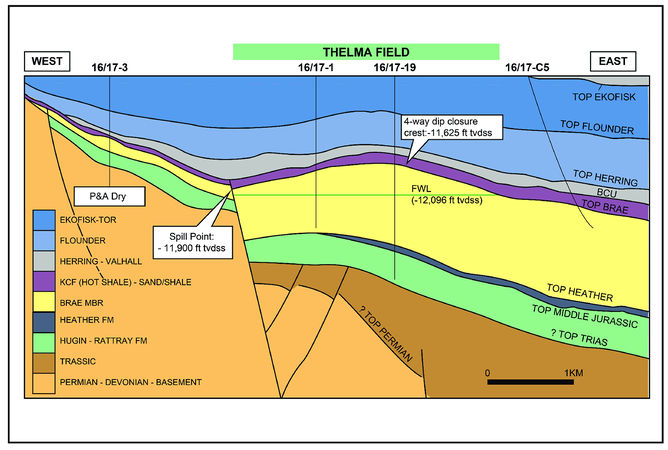
Figure 4 Geoseismic cross section through Thelma illustrating the Thelma free-water level relative to the independent four-way dip closure and the requirement for an additional trapping mechanism (line of section illustrated on Figure 2).
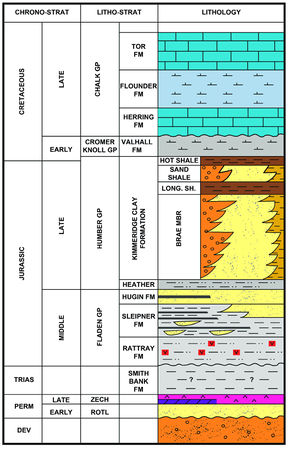
Figure 5 Simplified T-Block stratigraphy. Long. Sh. = Longicornis shale member.


Hydrocarbon distribution[edit]
Although the field is expressed as a relatively simple dip-closed structure at the Base Cretaceous level (Figure 2), this belies the complexity of the internal field stratigraphy. Within the field limits, there are at least five separate free water levels (FWLs) and two broadly different oil types, clearly demonstrating complex reservoir architecture and variable connectivity.
The Upper Jurassic isochron map (based on confident BCU and Top Middle Jurassic seismic events) reveals the complexity of the Late Jurassic basin within T-Block (Figure 6). Second-order structures within the hanging wall evident at the Top Middle Jurassic have created a complex of Late Jurassic depocenters into which the Upper Jurassic sediments accumulated. Details of the structural evolution that resulted in this complexity are addressed by Allerton et al. (2018[9]). On a larger scale, the Upper Jurassic interval is seen to thicken southward from the Thelma area and thin northward into the Toni region before thickening again northward into Tiffany. Toni therefore sits on a structural high that divides the graben into two segments within T-Block.
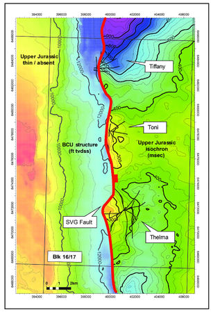
Figure 6 T-Block Upper Jurassic isochron map illustrating graben complexity and distribution of depocenters (development wells only).
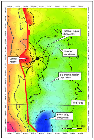
Figure 7 Upper Jurassic isochron map of the Thelma area illustrating the presence of a Middle Jurassic structural high under the Central region.
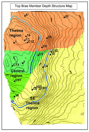
Figure 8 Thelma area regions (Top Brae member depth structure map). Blue lines represent some of the various free water levels illustrated in Figure 9.


More locally within the Thelma area, the Upper Jurassic isochron map reveals the presence of a Middle Jurassic structural high that existed beneath the central part of the BCU closure during the Late Jurassic (Figure 7). This high allows the Thelma area to be separated into three distinct regions (Figure 8), each with a different combination of FWLs and oil types:
- The Thelma region depocenter (C1Z producer)
- The Central region high (C5Y and C7X producers)
- The Southeast Thelma region depocenter (C2, C3Z, C4, and C8Y producers)
A north–south correlation illustrates the hydrocarbon-water contact complexity (Figure 9).
In the Thelma region, the Brae member oil pool has an FWL of 12,096 ft (3687 m) TVDss and a high gas-oil ratio (GOR: 2660 scf/bbl). The overlying sand-shale member has a lower GOR oil (∼1200 scf / bbl) but divides into an upper and a lower pool, each with a different FWL (11,577 ft [3528 m] TVDss and 11,777 ft [3589 m] TVDss, respectively). This is also evident from preproduction repeat formation tester (RFT) data (Figure 10). The Longicornis shale is 70 ft (21 m) thick in 16 /17-19 (core part of the Thelma main field) and is clearly sealing over geological time. A thin shale, only 10–15 ft (3–4.6 m) hick, divides the sand-shale member but still seals over geological time. This shale may correspond to the J71MFS.
In the Central region, both the Brae and sand-shale members comprise low NTG intervals. A 50 ft (15 m) sandstone occurs within the upper part of the Brae member in 16 / 17-C7X, which is oil bearing. The oil has a GOR similar to the Thelma region sand-shale member (GOR: approximately 1200 scf/bbl), with an ODT at 12,080 ft (3682 m) TVDss. Deeper porous intervals are water bearing with a water-up-to (WUT) of 12,180 ft (3712 m) TVDss. An oil-water contact (OWC) (from logs) is not observed, but Thomeer Function analysis (in-house) suggests an FWL at about 12,100 ft (3689 m) TVDss. While there may be some uncertainty about the FWL, it is clear from the oil type alone that there has to be a lateral seal between the Central and Thelma regions. An oil-bearing sandstone also occurs within the sand-shale member in well 16 /17-7, but there is insufficient data to conclude what the oil type or FWL is (no pre-production RFT data).
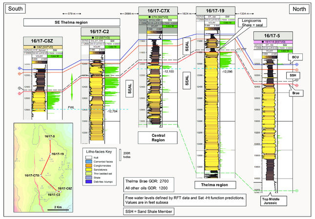
Figure 9 Thelma area well correlation illustrating the distribution of free water levels (horizontal dashed blue lines), intraformational seals, and the resultant compartmentalization of regions.
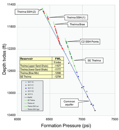
Figure 10 Thelma area preproduction formation pressure distribution illustrating different free water levels on a common aquifer pressure gradient that is overpressured by 1272 psi above hydrostatic.


In the Southeast Thelma region, both the Brae and sand-shale members are oil bearing. The oil has a GOR of 1186 scf/bbl in both members, and preproduction pressure data show that they are in pressure communication. However, the FWL is interpreted to be at 12,794 ft (3899 m) TVDss, 698 ft (21 m) deeper than the Thelma or Central regions. Therefore, while the Longicornis shale in Southeast Thelma is not sealing, there has to be a significant lateral seal between Southeast Thelma and both the Central and Thelma regions, sufficient to account for the large difference in contacts.
As there is a clear correlation between regions and FWLs and oil types, the question arises: What is the internal fan architecture and facies distribution that has resulted in this complexity and what was its cause? Gravity flow sediments by their very nature will travel downslope from their basin input point toward the depocenters. The route they take and where they deposit is dependent on depocenter architecture. The approach taken here was to map NTG and facies trends across the Thelma area to identify any correlation with depocenter distribution, and then build plausible facies models consistent with the data. The first step was to interpret facies for all the Thelma area wells.
See also[edit]
References[edit]
- ↑ Arduini, M., U. Biffi, S. T. J. Cherry, P. Gianni, A. Ortenzi, M. Rossi, N. C. T. Steel, and P. Terdich, 1993, Upper Jurassic deep-water heterogeneous reservoirs in the Thelma fields, UK North Sea, in A. M. Spencer, ed., Generation, accumulation and production of Europe’s hydrocarbons III: European Association of Petroleum Geoscientists Special Publication 3, p. 17–36.
- ↑ 2.0 2.1 Cherry, S. T. J., 1993, The interaction of structure and sedimentary process controlling deposition of the Upper Jurassic Brae Formation conglomerate, Block 16 /17, North Sea, in J. L. Parker, ed., Petroleum geology of northwest Europe: Proceedings of the 4th Conference, Geological Society (London), p. 387–400.
- ↑ 3.0 3.1 Kerlogue, A., S. Cherry, H. Davies, M. Quine, and G. Spotti, 1994, The Tiffany and Toni oil fields, Upper Jurassic submarine fan reservoirs, South Viking Graben, UK North Sea: Petroleum Geoscience, v. 1, p. 279–285.
- ↑ 4.0 4.1 Gambaro, M., and V. Donagemma, 2003, The T-Block Fields, Block 16/17, UK North Sea, in J. G. Gluyas and H. M. Hichens, eds., United Kingdom oil and gas fields, commemorative millennium volume: Geological Society (London) Memoir 20, p. 369–382.
- ↑ Turner, C. C., J. M. Cohen, E. R. Connell, and D. M. Cooper, 1987, A depositional model for the South Brae oilfield, in J. Brooks and K. W. Glennie, eds., Petroleum geology of northwest Europe: London, Graham & Trotman, p. 853–864.
- ↑ Bentley, M. R., and S. A. Smith, 2008, Scenario-based reservoir modelling: The need for more determinism and less anchoring, in A. Robinson, P. Griffiths, S. Price, J. Hegre, and A. Muggeridge, eds., The future of geological modelling in hydrocarbon development: Geological Society (London) Special Publication 309, p. 145–159.
- ↑ 7.0 7.1 Fraser, S. I., A. M. Robinson, H. D. Johnson, J. R. Underhill, D. G. A. Kadolsky, R. Connell, P. Johannessen, and R. Ravnas, 2003, Upper Jurassic, in D. Evans, C. Graham, A. Armour, and P. Bathurst, eds., The millennium atlas: Petroleum geology of the central and northern North Sea: Geological Society (London), p. 157–189.
- ↑ Harris, J. P., and R. M. Fowler, 1987, Enhanced prospectivity of the Mid–Late Jurassic sediments of the South Viking Graben, northern North Sea, in J. Brooks and K. W. Glennie, eds., Petroleum geology of northwest Europe: London, Graham & Trotman, p. 879–898.
- ↑ 9.0 9.1 Allerton, S., E. Giuliani, A. Kwiatkowski, M. A. Jones, J. Robinson, and A. Styles, 2018, Structural evolution of the T-Block fields, South Viking Graben, in C. C. Turner and B. T. Cronin, eds., Rift-related coarse-grained submarine fan reservoirs; the Brae Play, South Viking Graben, North Sea: AAPG Memoir 115, p. 543–564.
External links[edit]
| find literature about Thelma field |