Porosity
| Development Geology Reference Manual | |

| |
| Series | Methods in Exploration |
|---|---|
| Part | Laboratory methods |
| Chapter | Porosity |
| Author | M. Peter Cone, David G. Kersey |
| Link | Web page |
| Store | AAPG Store |
Porosity determines reservoir storage capacity. It is defined as the ratio of void space, commonly called pore volume, to bulk volume and is reported either as a fraction or a percentage. Almost all hydrocarbon reservoirs are composed of sedimentary rocks in which porosity values generally vary from 10 to 40% in sandstones and from 5 to 25% in carbonates.[1][2] (Also see Reservoir quality.)
Definition of porosity terms
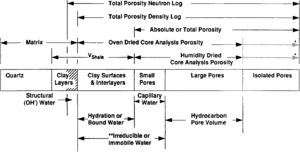
Discrepancies often exist between laboratory determined porosity values and porosities derived from downhole logs. Some of these discrepancies result from differences inherent in comparing direct measurements of physical properties made on small samples with indirect assessments of averaged properties. Many of these discrepancies, however, can be explained by noting differences in the definition and assessment of porosity (Figure 1).
Total porosity
Total porosity includes all void space regardless of whether the pores are interconnected or isolated. There is no practical way in the laboratory to measure isolated pore volume routinely on rocks. However, it can be determined by disaggregating the samples. If the disaggregated rocks contain smectite, the technique used to dry the samples can affect porosity values and the oven-dried total porosity will be larger than the humidity-dried total porosity (see Effective porosity below). Total porosity from a density log would equate with the disaggregated oven-dried total porosity from cores. The neutron log, however, would enlarge the definition to include structural hydroxyl chemistry.
Effective porosity
Oven-dried core analysis porosity includes the void space of all interconnected pores plus the volume of water bound to smectite. In contrast, humidity-dried core analysis porosity includes the void space of all interconnected pores plus the volume of all bound water in excess of the volume of a film of water, two molecules thick, retained by smectite. Keelan[2] reported that removal of this film may increase porosity 3.3 porosity points in rocks containing 10% smectite.
Pore types
Basic clastic and carbonate pore types can be identified by integrating data from core descriptions, thin section petrography, scanning electron microscopy, and capillary pressure tests. These analyses indicate that significant differences exist between clastic and carbonate pore types.
Sandstone pore systems
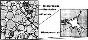
Four basic porosity types can be recognized in sandstones:[4] (1) intergranular (primary), (2) microporosity, (3) dissolution (secondary), and (4) fracture (Figure 2). Intergranular porosity exists as space between detrital grains. Microporosity exists as small pores (less than 2 μm) commonly associated with detrital and authigenic clay minerals. Dissolution porosity is the pore space formed from the partial to complete dissolution of framework grains and/or cements. Fracture porosity is the void space associated with natural fractures.
Carbonate pore systems
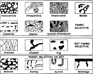
In comparison to clastic pore systems, pore types in carbonate rocks are more varied (see Carbonate reservoir models: facies, diagenesis, and flow characterization). Three basic pore groups can be recognized:[5] fabric selective, not fabric selective, and fabric selective or not (Table 1 and Figure 3). Seven porosity types (interparticle, intraparticle, intercrystal, moldic, fenestral, fracture, and vugs) are common and volumetrically important.
| Pore Type | Description |
|---|---|
| Fabric selective | |
| Interparticle | Porosity between particles |
| Intraparticle | Porosity within individual particles or grains |
| Intercrystal | Porosity between crystals |
| Moldic | Porosity formed by selective removal of an individual constituent of the rock |
| Fenestral | Pores larger than grain-supported interstices (interparticle) |
| Shelter | Porosity created by the sheltering effect of large sedimentary particles |
| Growth framework | Porosity created by in-place growth of a carbonate rock framework |
| Not fabric selective | |
| Fracture | Porosity formed by fracturing |
| Channel | Markedly elongate pores |
| Vug | Pores larger than 1/16 mm in diameter and somewhat equant in shape |
| Cavern | Very large channel or vug |
| Fabric selective or not | |
| Breccia | Interparticle porosity in breccia |
| Boring | Porosity created by boring organism |
| Burrow | Porosity created by organism burrowing |
| Shrinkage | Porosity produced by sediment shrinkage |
Although fracture porosity is very common in carbonate rocks, it is generally less than 1% of the bulk volume in both clastic and carbonate reservoirs.
Influence of textural parameters on porosity
Primary porosity in clastic and some carbonate rocks (such as oolites) is a function of grain size, packing, shape, sorting, and amount of intergranular matrix and cement.[8] In theory, porosity is independent of grain size. Changes in grain size, however, affect grain shape and sorting. Because these variables directly affect porosity, changes in grain size indirectly affect porosity.
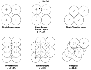
The theoretical effects of grain size and packing on porosity were investigated by Graton and Fraser[7] who computed the porosity of various packing arrangements of uniform spheres. The theoretical maximum porosity for a cubic packed rock, regardless of the value assigned to grain radius, is 47.6%. Porosity values for other packing arrangements (Figure 4) can be calculated.
The effects of grain shape on primary porosity were investigated by Fraser[9] and Beard and Weyl.[10] In general, porosity decreases as sphericity increases due to tighter packing arrangements associated with spherical grains. Numerous studies[9][11][10][12] indicate that porosity generally increases with sorting. Gaither[13] showed that when two grain sizes are mixed, porosity is reduced until both grain sizes are present in approximately equal amounts.
Laboratory determination of porosity
Sample preparation
Most porosity analysis techniques require removal of soluble hydrocarbons before sample analysis. Factors influencing sample cleaning include the types of hydrocarbon present, the presence of salts precipitated from pore waters, rock mineralogy, degree of cementation, and time constraints. Different solvents and cleaning techniques can be used to remove hydrocarbons from rocks. Toluene is generally an effective solvent for most liquid hydrocarbons. If hydrocarbons cannot be removed with toluene, toluene/methanol (azeotrope), chloroform/methanol (azeotrope), methylene chloride or carbon disulfide may be used. Methanol is used to remove salts formed from the evaporation of saline pore waters. Rocks containing gypsum and smectite require special low temperature cleaning techniques to minimize removal of structural and bound water.[14]
Laboratory determination of porosity generally requires dry samples. Most clay-free samples can be dried in an oven (temperature::115°C). If clay minerals, especially smectite, are present, humidity drying (45% relative humidity, temperature::63°C) is required to prevent removal of clay-bound water.
Laboratory analysis
Various laboratory techniques are available to determine porosity. Sample type, pore types, time constraints, and accuracy requirements are generally used to determine the best analytical technique (Table 2).
| Method | Advantages |
|---|---|
| Resaturation porosity | Accurate |
| Saturated samples available for further testing | |
| Saturation time is dependent on permeability | |
| Boyle's law porosity: grain volume determination | Very accurate |
| Not sensitive to rock mineralogy | |
| Samples can be used for further testing | |
| Grain density readily determined | |
| Irregularly shaped, fractured, and/or vuggy samples easily measured | |
| Rapid technique (after cleaning and drying) | |
| Boyle's law porosity: pore volume determination | Very accurate |
| Not sensitive to rock mineralogy | |
| Porosity can be determined at reservoir stress | |
| Permeability can be run on same apparatus to avoid stress hysteresis | |
| Rapid technique (after cleaning and drying) | |
| Summation of fluids porosity | Accurate for most rock types |
| Porosity and saturation determined on sample splits | |
| Requires no cleaning or drying | |
| Rapid technique | |
| Thin section porosity point count | Porosity can be determined on irregular, fractured, and/or vuggy samples |
| Pore types can be identified | |
| Grain, cement, matrix, and pore relationships can be established | |
| P.I.A. porosity | Porosity can be determined on irregular shapes |
| Pore types can be identified | |
| Precise determination of visible porosity |
Porosity can be determined by measuring two of three variables: pore volume (Vp), bulk volume (Vb), or grain volume (Vg). Equations 1, 2, or 3 are then used to compute porosity:
Porosity can also be determined by adding (using summation of fluids) the individual ratios of gas volume to bulk volume (Gb), oil volume to bulk volume (Ob), and water volume to bulk volume (Wb) (Equation 4). Thus,
Pore volume measurement
Pore volume can be measured directly by resaturating a clean, dry rock with a fluid. Resaturation is done with either gas (Boyle's law method) or liquid (gravitational method).
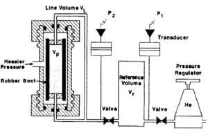
In the Boyle's law method, helium is used to saturate the sample because it is inert, not easily adsorbed onto mineral surfaces, and (due to its small molecular size) rapidly enters the micropore system. In the laboratory, the core is often placed in an apparatus consisting of a flexible rubber boot inside a core holder (Figure 5). Pressure is then applied to the outside of the rubber boot to seat it against the sample. Helium from a reference cell at known pressure is then expanded into the pore volume. The new equilibrium pressure in the system is monitored, and the pore volume is calculated from Boyle's law:
where
- P1 = initial pressure in the reference cell
- P2 = final pressure in the system
- Vr = volume of reference cell
- VL = volume of connecting tubing (line volume)
- Vp= pore volume of sample
Very accurate measurements of pore volume can be achieved with a Boyle's law porosimeter if the boot conforms to the sample. Consequently, this technique is not suited for vuggy or fractured rocks or for samples that cannot be trimmed into cylinders.
In the gravitational method, a cleaned and dried sample is first weighed and then immersed in a saturating vessel. The vessel is filled with a saturating liquid and pressured to 2000 psi for a minimum of 24 hours. After the pressure stabilizes, the fully saturated sample is removed from the saturator, immediately rolled on an absorbent material to remove the surface film of saturating fluid, and weighed. Pore volume is calculated from the following equation:
where
- Vp = pore volume
- WS = weight of sample (100% saturated)
- Wd = weight of sample (dry)
- ρs = density of saturating liquid
This technique is not suited for vuggy, fractured, or very low permeability samples.
Grain volume measurement
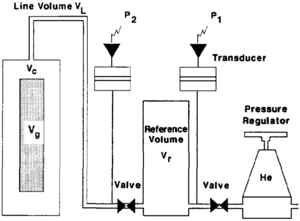
Grain volume can also be measured by the Boyle's law method. The equipment used to measure grain volume and pore volume are similar with the exception of the sample chamber. The grain volume porosimeter does not confine the sample by means of a rubber boot (Figure 6). To measure grain volume, the sample is placed into a chamber of known volume. Helium, from a reference cell at known pressure, is then expanded into the sample chamber. The equilibrium pressure of the system is monitored and Boyle's Law is used to calculate the grain volume. Therefore,
where
- P1 = initial pressure in the reference cell
- P2 = final pressure in the system
- Vr = volume of reference cell
- Vc = volume of sample chamber
- VL = volume of connecting tubing (line volume)
- Vg = grain volume of sample (unknown)
This is an excellent method to determine the grain volume regardless of the samples shape or surface characteristics.
Bulk volume measurement
Bulk volume can be determined by direct measurement, by fluid displacement, or gravimetrically. Calipers can be used to measure uniform samples directly, and bulk volume is calculated from the measured dimensions. This technique is not suited for noncylindrical samples.
Bulk volume can also be determined by immersing a small sample in a nonwetting fluid. Mercury is generally used as the nonwetting fluid, and the bulk volume is equal to the volume of mercury displaced by the sample. The gravimetric determination of bulk volume is similar to the saturation procedure used to determine pore volume. The fully saturated sample is first weighed in air, and reweighed while immersed in the wetting fluid. The bulk volume is calculated from Archimedes' principle. Thus,
where
- Vb = bulk volume
- Ws = weight of sample in air (100% saturated)
- Wi = weight of sample immersed in saturating liquid
- ρs = density of saturating liquid
Summation of fluids (Retort Porosity) technique
The summation of fluids method is a rapid analytical technique of determining porosity by using the assumption that the total volume of the oil, water, and gas in a material constitutes the pore volume of that material. The former two values are determined through retorting to the samples at elevated temperature and the latter by direct mercury injection. (For more on summation of fluids, see Overview of routine core analysis.)
Other techniques
Another technique available for the determination of porosity in addition to those mentioned here is point counting pore space occupied by blue epoxy in thin sections (see Thin section analysis). Also, significant progress has been made recently in the development of petrographic image analysis (PIA) as a technique for porosity determination.[15][16] In this process, pore space is delineated from mineralogy using photographic imaging techniques. Taking images from several locations on a thin section allows one to compensate for a three-dimensional parameter from two dimensions.
Both X-ray computerized tomography (CT) and nuclear magnetic resonance (NMR) have applications to determining porosity. This is outside the scope of this discussion but is comprehensively covered in the literature (e.g., Vinegar,[17] and Wellington and Vinegar[18]).
Effects of confining pressure on porosity
Porosity decreases with increasing net overburden pressure (lithostatic pressure minus pore pressure), and in clastic rocks, stress sensitivity generally increases with increasing clay and decreasing cement content.[19] Because porosity is stress dependent, laboratory measurements should be made at stress conditions whenever possible. These measurements are done with specially designed Boyle's law (pore volume) porosimeters, similar to that shown in Figure 5, which apply hydrostatic stress to the sample. In the reservoir, however, the resolved stress component is uniaxial. Uniaxial stress is less than hydrostatic stress, and consequently, the hydrostatic strain measured in the laboratory should be converted to an equivalent reservoir (uniaxial) strain.
See also
- Core description
- Relative permeability and pore type
- Paleontology
- Wettability
- Oil and condensate analysis
- Capillary pressure
- Oilfield water analysis
- Permeability
- SEM, XRD, CL, and XF methods
- Thin section analysis
- Rock-water reaction: formation damage
- Overview of routine core analysis
- Core-log transformations and porosity-permeability relationships
References
- ↑ Coneybeare, C. E. B., 1967, Influence of compaction on stratigraphic analysis: Canadian Petroleum Geology Bulletin, v. 15, p. 331–345.
- ↑ 2.0 2.1 Keelan, D. K., 1982, Core analysis for aid in reservoir description: Journal of Petroleum Technology, v. 34, p. 2483–2491, DOI: 10.2118/10011-PA.
- ↑ Chatzis, I., N. R. Morrow, and H. T. Lim, 1983, Magnitude and detailed structure of residual oil saturation: Society Petroleum Engineers Journal, v. 23, p. 311–326., 10., 2118/10681-PA
- ↑ 4.0 4.1 Pittman, E. D., 1979, Porosity, diagenesis, and productive capability of sandstone reservoirs, in P. A. Scholle, and P. R. Schluger, eds., Aspects of Diagenesis: Society Economic Paleontologists and Mineralogists Special Publication 26, p. 159–173.
- ↑ 5.0 5.1 Choquette, P. W., and L. C. Pray, 1970, Geological nomenclature and classification of porosity in sedimentary carbonates: AAPG Bulletin, v. 54, p. 207–250.
- ↑ Berg, R. R., 1970, Method for determining permeability from reservoir rock properties: Transactions Gulf Coast Association of Geological Societies, v. 20, p. 303–317.
- ↑ 7.0 7.1 Graton, L. C., and H. J. Fraser, 1935, Systematic packing of spheres with particular reference to porosity and permeability: Journal of Geology, v. 43, p. 785–909, DOI: 10.1086/jg.1935.43.issue-8.
- ↑ Pettijohn, F. J., 1975, Sedimentary rocks, 3rd ed.: New York, Harper and Row, p. 628.
- ↑ 9.0 9.1 Fraser, H. J., 1935, Experimental study of porosity and permeability of clastic sediments: Journal of Geology, v. 43, p. 910–1010, DOI: 10.1086/jg.1935.43.issue-8.
- ↑ 10.0 10.1 Beard, D. C., and P. K. Weyl, 1973, Influence of texture on porosity and permeability of unconsolidated sand: AAPG Bulletin, v. 57, p. 349–369.
- ↑ Rogers, J. J., and W. Head, 1961, Relationship between porosity, median size and sorting coefficients of synthetic sands: Journal of Sedimentary Petrology, v. 31, p. 467–470.
- ↑ Pryor, W. A., 1973, Permeability-porosity patterns and variations in some Holocene sand bodies: AAPG Bulletin, v. 57, n. 1, p. 162–189.
- ↑ Gaither, A., 1953, A study of porosity and grain relationships in experimental sands: Journal of Sedimentary Petrology, v. 23, p. 180–195, DOI: 10.1306/D4269602-2B26-11D7-8648000102C1865D.
- ↑ Keelan, D. K., 1971, A critical review of core analysis techniques: 22nd Annual Technical Meeting of the Petroleum Society of the Canadian Institute of Mining, Calgary, Banff, Alberta, June 2–5, Paper No. 7612, p. 1–13.
- ↑ Ehrlich, R., S. K. Kennedy, S. J. Crabtree, and R. C. Crabtree, 1984, Petrographic image analysis, 1. Analysis of reservoir pore complexes: Journal of Sedimentary Petrology, v. 54, n. 4, p. 1365–1378.
- ↑ Gerard, R. E., C. A. Philipson, F. M. Bellentine, and D. H. Marshall, 1991, Petrographic image analysis, in Polaz, I., Sengupta, S. K., eds., Automated Pattern Analysis in Petroleum Exploration: New York, Springer-Verlag.
- ↑ Vinegar, H. J., 1986, X-ray, CT, and NMR imaging of rocks: Journal of Petroleum Technology, v. 38, p. 257–259, DOI: 10.2118/15277-PA.
- ↑ Wellington, S. L., and H. J. Vinegar, 1987, X-ray computerized tomography: Journal of Petroleum Technology, v. 39, n. 8, p. 885–898, DOI: 10.2118/16983-PA.
- ↑ Amaefule, J. O., D. K. Keelan, D. G. Kersey, and D. M. Marschall, 1988, Reservoir description—a practical synergistic engineering and geological approach based on analysis of core data: 63rd SPE Annual Technical Conference and Exhibition of the Society of Petroleum Engineers, Houston, TX, October 2–5, SPE 18167.
External links
- Original content in Datapages
- Find the book in the AAPG Store
- Porosity in SubSurfWiki
